Fire hose placement device of fire fighting truck

A technology for fire hoses and fire trucks, applied in fire rescue and other directions, can solve the problems of cumbersome operation and inconvenience in taking fire hoses, and achieve the effect of increasing the control method and increasing the speed of taking.

Inactive Publication Date: 2020-12-04
邓永琦
View PDF11 Cites 0 Cited by
  • Summary
  • Abstract
  • Description
  • Claims
  • Application Information

AI Technical Summary

Problems solved by technology

[0003] The structure of the device used to place the fire hose in the fire truck largely determines the time it takes for the firefighters to take the fire hose. Existing fire trucks generally place the fire hose through the storage cabinet. The fire hoses are stacked vertically, which is inconvenient to take multiple fire hoses at the same time, and the cabinet door needs to be opened manually, which is cumbersome to operate

Method used


Image

  • Fire hose placement device of fire fighting truck
  • Fire hose placement device of fire fighting truck
  • Fire hose placement device of fire fighting truck

Examples


Embodiment 1

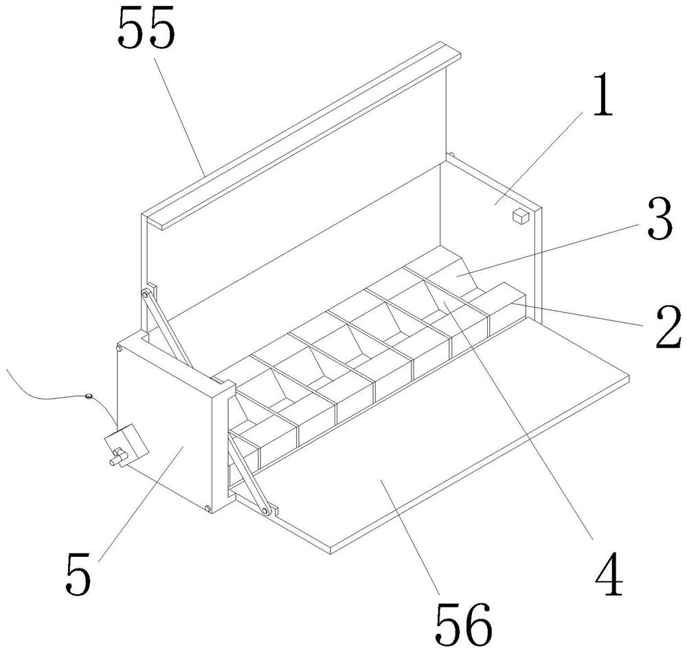
[0028] see figure 1 and figure 2 , the present invention provides a fire hose placement device for a fire truck through improvement, including a casing 1 and an opening and closing device 5. The inner bottom of the casing 1 is locked with the support seat 2 by bolts, and a concave hole is opened in the middle of the support seat 2. Groove 3, and a partition plate 4 is vertically arranged inside the groove 3, the left side of the shell 1 is locked with the opening and closing device 5 by bolts, the inner wall of the groove 3 is smooth, and the length of the groove 3 is from top to Lower taper for easy placement and support of fire hose.

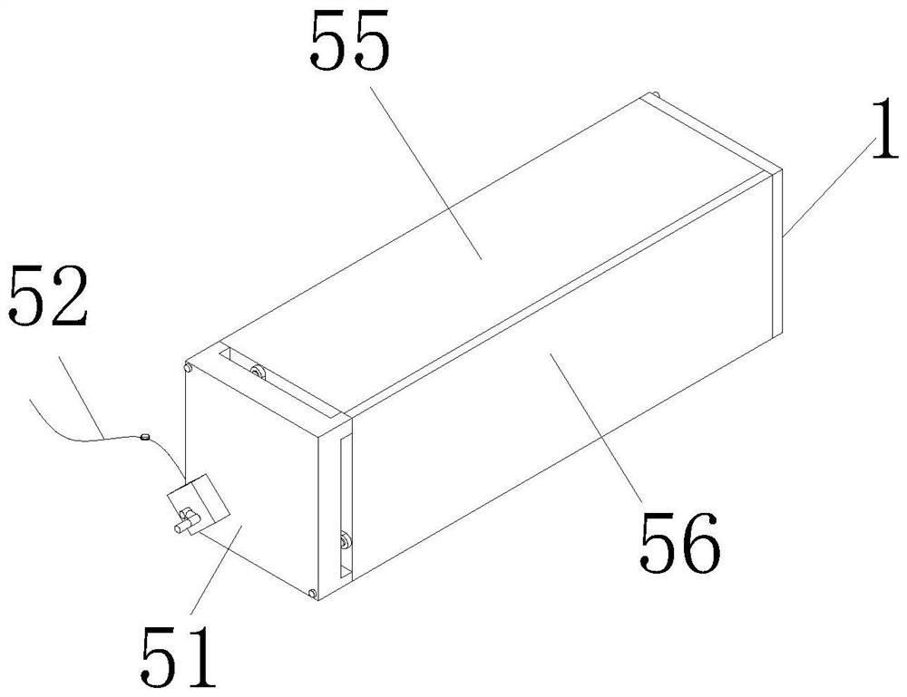
[0029] see image 3 , the present invention provides a fire hose placement device for a fire truck through improvement. The opening and closing device 5 includes a control mechanism 51, a power cord 52, a first connecting rod 53, a second connecting rod 54, an upper cover 55 and a The cover plate 56, the rear end of the control mechanism 5...

Embodiment 2

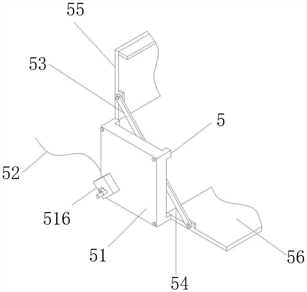
[0033] The present invention provides a fire hose placement device for a fire truck through improvement. The second connecting rod 54 is arranged obliquely, and the second connecting rod 54 is inclined downward from back to front, so that the movable shaft 514 passes through when moving downward. The second connecting rod 54 pulls the front cover 56 to rotate downwards, the left and right sides of the upper cover 55 and the front cover 56 are smooth, and the inner wall of the housing 1 is bonded to the upper cover 55 and the front cover 56. The upper cover 55 and the front cover 56 close the top end and the front side of the casing 1 .

[0034]The present invention provides a fire hose placement device for a fire truck through improvement, and its working principle is as follows;

[0035] First, before use, first install the shell 1 of the device on the required fire truck, and connect the power line 52 with an external control device with a power supply, and control the motor...


PUM


Abstract

The invention discloses a fire hose placement device of a fire fighting truck. The fire hose placement device of the fire fighting truck comprises a shell, a supporting base, a groove, partition boards and an opening and closing device. According to the fire hose placement device of the fire fighting truck, by arranging the opening and closing device on the outer side of the shell where fire hosesare placed, the top end and the front side of the shell are covered by the opening and closing device through an upper cover board and a front cover board, by driving a motor in a control mechanism,the upper cover board and the front cover board can be opened at the same time, by adopting an electric control mode, when the fire hoses need to be taken, the upper cover board and the front cover board are opened in advance, thus the speed of taking the fire hoses is improved, by arranging a manual driving mechanism on a screw in the control mechanism, in a circuit failure situation, opening ofthe upper cover board and the front cover board is controlled by adopting a manual mode, thus the control mode of the control mechanism is increased, and the situation that the fire hoses cannot be taken when a circuit fails is avoided.

Description

technical field [0001] The invention relates to the related field of fire fighting equipment, in particular to a fire hose placement device for a fire truck. Background technique [0002] Fire hose is one of the important equipment of fire trucks. At present, fire trucks with fire extinguishing function or vehicles equipped with on-board fire pumps, such as elevating jet fire trucks, climbing platform fire trucks, ladder fire trucks, foam fire trucks, Water tank fire trucks, compressed air foam fire trucks, foam dry powder combined fire trucks, water tank dry powder combined fire trucks, etc., are all equipped with DN65 or DN80 medium or low pressure fire hoses. [0003] The structure of the device used to place the fire hose in the fire truck largely determines the time it takes for the firefighters to take the fire hose. Existing fire trucks generally place the fire hose through the storage cabinet. The fire hoses are stacked vertically, which is inconvenient to take mult...

Claims


Application Information

Patent Timeline
Patent Type & Authority Applications(China)
IPC IPC(8): A62C33/04A62C27/00
CPCA62C27/00A62C33/04
Inventor 邓永琦
Owner 邓永琦
Why Eureka
Try Eureka