Safety swing capable of realizing active braking and active protection

A technology of active protection and active braking, which is applied in swings, entertainment, entertainment devices, etc., can solve the problems of low safety of swings and occupants falling off, and achieve the effect of avoiding excessive braking force, ensuring stability and increasing comfort

Active Publication Date: 2020-12-04
临沂瑞钢联管业有限公司
View PDF8 Cites 1 Cited by
  • Summary
  • Abstract
  • Description
  • Claims
  • Application Information

AI Technical Summary

Problems solved by technology

[0007] Aiming at the deficiencies of the prior art, the present invention provides a safety swing that realizes active braking and active protection, which solves the problem that the safety of the traditional swing is low. The problem of falling off the seat

Method used


Image

  • Safety swing capable of realizing active braking and active protection
  • Safety swing capable of realizing active braking and active protection
  • Safety swing capable of realizing active braking and active protection

Examples


Embodiment 1

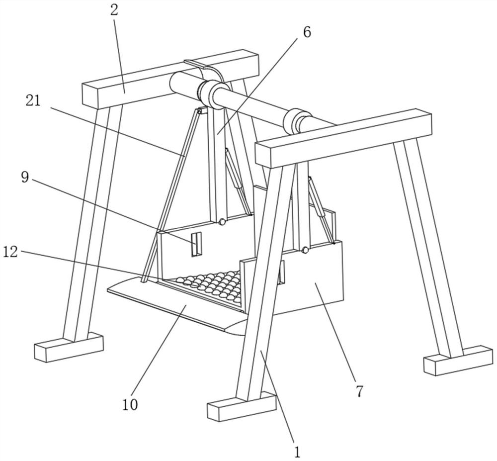
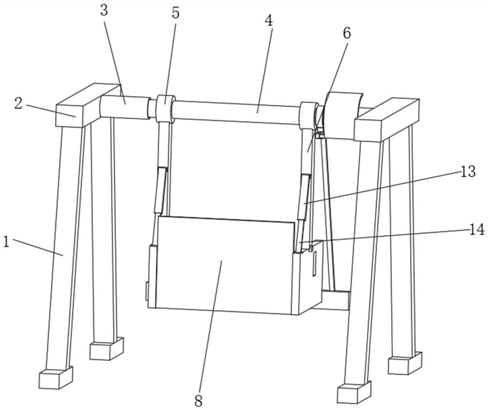
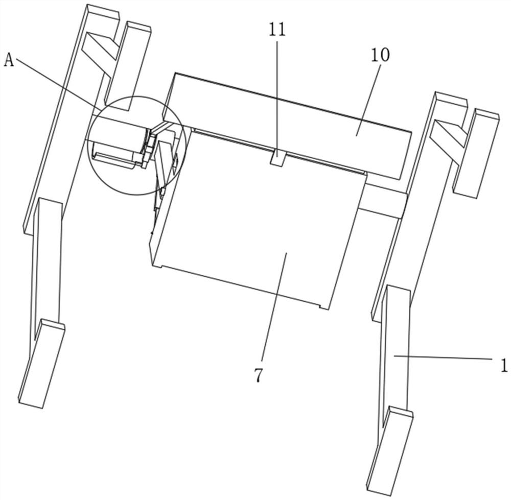
[0035] like Figure 1-4 As shown, the present invention provides a technical solution: a safety swing that realizes active braking and active protection, comprising an outer support frame 1, and a support mandrel 2 is fixedly connected to the middle position of the top of the outer support frame 1, and the inner side of the support mandrel 2 is fixedly connected. The middle position is fixedly connected with a limiting plunger 3, the interior of the limiting plunger 3 is penetrating and rotatably connected with a rolling shaft 4, the left and right ends of the outer rolling shaft 4 are sleeved and rotatably connected with a supporting bushing 5, the supporting shaft The bottom of the sleeve 5 is fixedly connected with a support rocker 6, the bottom of the support rocker 6 is rotatably connected with a support seat frame 7, the back of the support seat frame 7 is fixedly connected with a support back plate 8, and both sides of the support seat frame 7 close to the front are fixe...

Embodiment 2

[0040] like Figure 5-6 As shown, on the basis of the first embodiment, the present invention provides a technical solution: a safety swing that realizes active braking and active protection. There is an auxiliary hanging rod 18 , and one end of the auxiliary hanging rod 18 away from the rolling shaft 4 is fixedly connected with an inner limiting groove 19 .

[0041] The inner limit slot 19 penetrates through and is slidably connected with a movable plunger 20. One end of the movable plunger 20 located outside the inner limit slot 19 is rotatably connected with a brake linkage rod 21. The top of the transmission pedal 10 is connected in rotation.

[0042] A brake pad 22 is fixedly connected to the end of the movable plunger 20 located outside the inner limiting groove 19 and away from the brake linkage rod 21 . When the swing of the swing is too large, active braking is realized, and the braking potential energy is larger, thereby ensuring that the occupants can move within ...


PUM


Abstract

The invention relates to a safety swing capable of realizing active braking and active protection, which comprises an outer supporting frame, a limiting inserting rod is fixedly connected to the middle of the inner side of a supporting ejector rod, a rolling shaft rod penetrates through the limiting inserting rod and is rotatably connected to the interior of the limiting inserting rod, and supporting shaft sleeves are arranged at the left end and the right end of the exterior of the rolling shaft rod in a sleeving mode and are rotatably connected to the left end and the right end; a supportingrocker is fixedly connected to the bottom of the supporting shaft sleeve, a supporting seat frame is rotatably connected to the bottom of the supporting rocker, a safety transmission pedal is rotatably connected to the bottom of the front face of the supporting seat frame, and the middle of the bottom of the safety transmission pedal is fixedly connected with the front face of the bottom of the supporting seat frame through supporting springs; and buffer balls are uniformly and fixedly connected to the surface of the top end of the interior of the supporting seat frame. The invention relatesto the technical field of swings. According to the safety swing, when the forward swing amplitude of the swing is too large, active braking is achieved, the braking potential energy is large, and therefore it is guaranteed that passengers move within the safe swing range.

Description

technical field [0001] The invention relates to the technical field of swings, in particular to a safety swing that realizes active braking and active protection. Background technique [0002] The swing is used as a game device. The long rope is tied to the shelf, and the pedal board is hung from the bottom, and the person swings back and forth with the pedal board. Swing is a sport created by ethnic minorities in northern China in ancient times. [0003] For example, the Chinese Invention Publication No. is: CN1419876A, a baby swing, wherein the electromagnet is used to automatically swing the swing. A swing frame supporting a pair of booms is connected with the upper ends of the booms, a pair of swingers respectively extend from the pair of booms, and a swing is formed at the lower end of each swinger. A pair of electromagnets are arranged on both sides of the pendulum, so that the pendulum can oscillate repeatedly and continuously. The rack has a pair of tops from whic...

Claims


Application Information

Patent Timeline
Patent Type & Authority Applications(China)
IPC IPC(8): A63G9/00A63G9/22
CPCA63G9/00A63G9/22
Inventor 冷明宇
Owner 临沂瑞钢联管业有限公司
Why Eureka
Try Eureka