Television frame manufacturing feeding mechanism

A feeding mechanism and TV technology, which is applied in the direction of manufacturing tools, metal processing equipment, feeding devices, etc., can solve the problems that it is difficult to ensure the position deviation of TV frame profiles, increase manufacturing costs, etc.

Pending Publication Date: 2020-12-04
湖南捷创新材料有限公司
View PDF0 Cites 2 Cited by
  • Summary
  • Abstract
  • Description
  • Claims
  • Application Information

AI Technical Summary

Problems solved by technology

Due to the large size of the TV, the frame of the TV is very long before bending, and the cross-section of the profile of the TV frame is generally irregular in shape. Since the frame of the TV is very long, it is necessary to bend the TV The frame profile is sent to the bending process. In this process, it is often difficult to ensure that the TV frame profile will not be shifted during the transmission process; in addition, due to the particularity of the TV frame profile in size and shape, in order to To improve production efficiency and ensure the timeliness of material delivery, it is often necessary to arrange multiple labors to load materials, thus increasing the manufacturing cost

Method used


Image

  • Television frame manufacturing feeding mechanism
  • Television frame manufacturing feeding mechanism
  • Television frame manufacturing feeding mechanism

Examples


Embodiment Construction

[0038] In order to make the object, technical solution and advantages of the present invention clearer, the following will further describe the TV frame manufacturing and feeding mechanism of the present invention in detail with reference to the accompanying drawings and embodiments. It should be understood that the specific embodiments described here are only used to explain the present invention, not to limit the present invention.

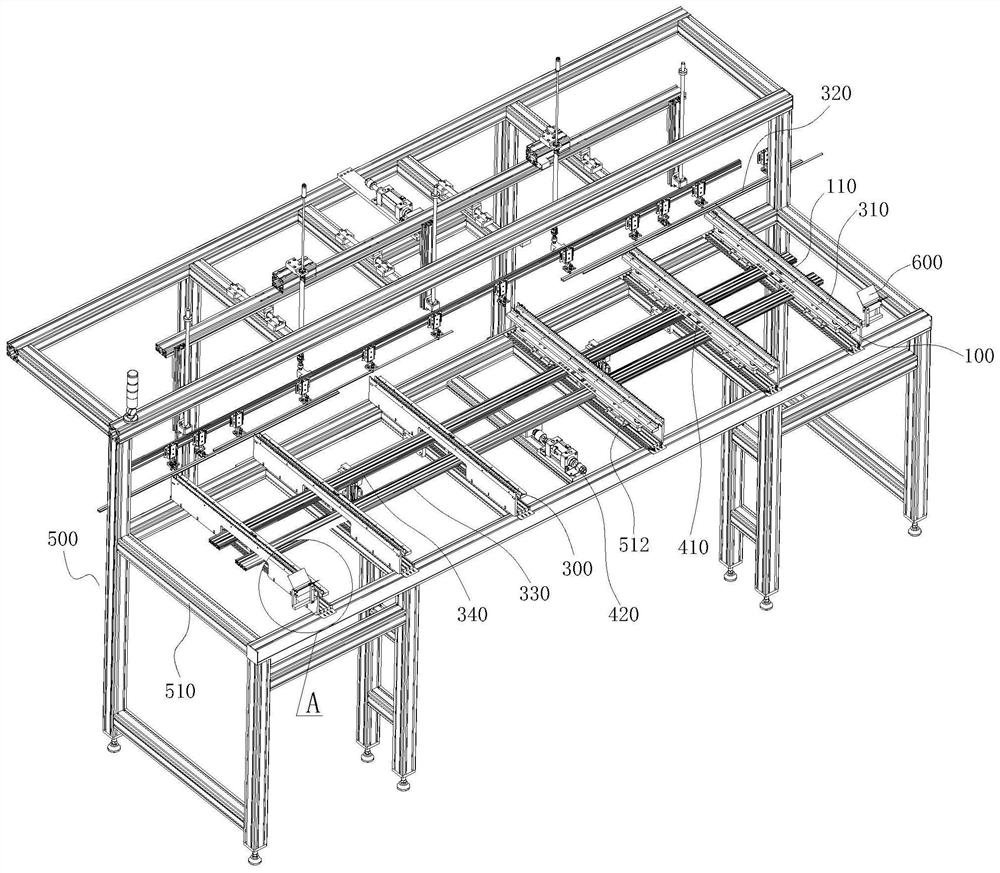
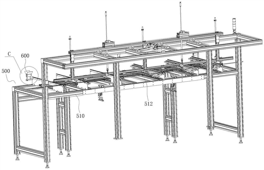
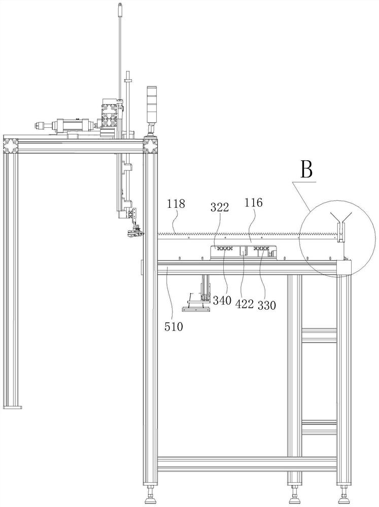
[0039] See Figure 1 to Figure 3 and Figure 5 , a TV frame manufacturing feeding mechanism according to an embodiment of the present invention, comprising:

[0040] The fixed feeding unit 100 is used to place the frame profile 200 placed in a certain direction. The cross-sectional shape of the frame profile 200 is an irregular shape, and multiple support points are needed to support the frame profile stably;

[0041] The feeding unit 300 is used to move the frame profile 200 placed on the fixed feeding unit 100 forward;

[0042] A drive unit, ...


PUM


Abstract

The invention relates to a television frame manufacturing feeding mechanism. The television frame manufacturing feeding mechanism comprises a fixed feeding unit, a material conveying unit and drivingunits, wherein the fixed feeding unit comprises a first material placing plate, a plurality of first tooth grooves are formed in the top of the first material placing plate, the material conveying unit comprises a second material placing plate, the second material placing plate is parallel to the first material placing plate and is lower than the horizontal position of the first material placing plate, after the second material placing plate moves upwards to be higher than the horizontal position of the first material placing plate through a vertical driving unit, the frame profile and secondtooth grooves are fixed and separated from the first tooth grooves, the second material placing plate moves forwards through a horizontal driving unit to enable the frame profile to move to the position above the front adjacent first tooth grooves, then the second material placing plate moves downwards through the vertical driving unit to enable the frame profile to be fixed to the first tooth grooves adjacent to the front face, and finally the second material placing plate moves backwards to the original position through the horizontal driving unit. The television frame manufacturing feedingmechanism has the advantages of being free of displacement deviation in the conveying process, high in automation degree and low in manufacturing cost.

Description

technical field [0001] The invention relates to a feeding mechanism, in particular to a feeding mechanism for TV frame manufacturing. Background technique [0002] With the continuous improvement of people's living standards, people's requirements for TV sets are also increasing day by day, and TV sets are becoming thinner and larger in size. Due to the large size of the TV, the frame of the TV is very long before bending, and the cross-section of the profile of the TV frame is generally irregular in shape. The frame profile is sent to the bending process. In this process, it is often difficult to ensure that the TV frame profile will not be shifted during the transmission process; in addition, due to the particularity of the TV frame profile in size and shape, in order to To improve production efficiency and ensure the timeliness of material delivery, it is often necessary to arrange multiple labors to load materials, thus increasing the manufacturing cost. Contents of t...

Claims


Application Information

Patent Timeline
IPC IPC(8): B21D43/00
CPCB21D43/006
Inventor 陈余鑫张思华王大利郑孝存杨柳谭爱明
Owner 湖南捷创新材料有限公司
Why Eureka
Try Eureka