Forging equipment for steel manufacturing

A kind of equipment and steel technology, which is applied in the field of forging equipment for steel manufacturing, can solve the problems of staff physical investment, hidden dangers of staff health, heavy steel parts, etc., and achieve the effect of avoiding a large amount of consumption

Inactive Publication Date: 2020-12-04
徐子敏
View PDF10 Cites 3 Cited by
  • Summary
  • Abstract
  • Description
  • Claims
  • Application Information

AI Technical Summary

Problems solved by technology

[0002] In the existing technology, during the process of steel forging through dies, it is generally still in the state of manual clamping. The staff hold X-shaped clamps to clamp the external mold and the manufactured parts of the steel parts respectively, and pass through the equipment. The lowering of the mold is used to forge the mold, and in the process of processing, the position and angle of the mold need to be adjusted, all of which are manually adjusted. Generally, the steel parts that need to be forged are heavy, and frequent manual adjustments are very difficult. It is easy to cause investment in the physical strength of the staff, and the continuous forging work will bring a lot of hidden dangers to the health of the staff

Method used


Image

  • Forging equipment for steel manufacturing
  • Forging equipment for steel manufacturing
  • Forging equipment for steel manufacturing

Examples


Embodiment Construction

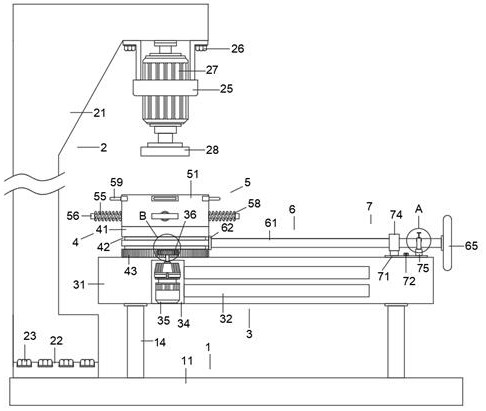
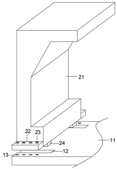
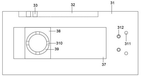
[0032] Such as Figure 1-9As shown, this specific embodiment adopts the following technical solutions: a forging equipment for iron and steel manufacturing, including a base mechanism 1, and the base mechanism 1 includes a fixed base 11, a No. 1 chute 12, a No. 1 screw groove 13 and a support column 14 , the four corners on one side of the top of the fixed base 11 are fixed with support columns 14, and the top of the fixed base 11 is excavated with two No. A number of No. 1 screw grooves 13 are excavated on the sides of the two No. 1 chutes 12 away from each other. The fixed base 11 is connected to the forging mechanism 2 through the two No. 1 chute 12 and a number of No. 1 screw grooves 13 on both sides. The top parts of the four support columns 14 are fixedly connected to the four corners of the bottom of the limit sliding mechanism 3, and the top side of the limit sliding mechanism 3 is connected with a rotating mechanism 4, and the rotating mechanism 4 is far away from the...


PUM


Abstract

The invention discloses forging equipment for steel manufacturing. The equipment comprises a base mechanism, the base mechanism comprises a fixed base, first sliding grooves, first screw grooves and supporting columns, the supporting columns are fixed to the four corners of one side of the top of the fixed base correspondingly, and the two first sliding grooves are dug at the side, away from the four supporting columns, of the top of the fixed base. The plurality of first screw grooves are dug at the sides, where the two first sliding grooves are away from each other, of the top of the fixed base. Through the arrangement of a forging mechanism, steel and iron manufacturing parts can be conveniently forged, and during machining, through cooperation use of a limiting sliding mechanism, a rotating mechanism, a machining mechanism, a dragging mechanism and a limiting mechanism, movable operation work of manual clamping, limiting and angle adjusting of the manufacturing parts can be replaced, and the problem that the body of a worker is damaged due to the fact that the physical strength of the worker is greatly consumed is solved.

Description

Technical field: [0001] The invention belongs to the technical field of forging equipment, in particular to a forging equipment for iron and steel manufacturing. Background technique: [0002] In the existing technology, during the process of steel forging through dies, it is generally still in the state of manual clamping. The staff hold X-shaped clamps to clamp the external mold and the manufactured parts of the steel parts respectively, and pass through the equipment. The lowering of the mold is used to forge the mold, and in the process of processing, the position and angle of the mold need to be adjusted, all of which are manually adjusted. Generally, the steel parts that need to be forged are heavy, and frequent manual adjustments are very difficult. It is easy to cause investment in the physical strength of the staff, and the continuous forging work will bring considerable hidden dangers to the health of the staff. Invention content: [0003] It is an object of the...

Claims


Application Information

Patent Timeline
Patent Type & Authority Applications(China)
IPC IPC(8): B21J7/04B21J13/10
CPCB21J7/04B21J13/10
Inventor 徐子敏
Owner 徐子敏
Why Eureka
Try Eureka