
Rapid positioning and welding device of thin-wall special-shaped pull rod and forming and welding method thereof

A positioning welding and tie rod technology, which is applied in welding equipment, auxiliary equipment, welding equipment, etc., can solve the needs of new models and new model development, which cannot meet the welding needs of thin-walled special-shaped tie rods, and the structure of thin-walled special-shaped tie rods is complex And other problems, to achieve the effect of good rigidity, beautiful appearance, and less shape restrictions

Inactive Publication Date: 2020-12-04
HUBEI SANJIANG AEROSPACE WANFENG TECH DEV
View PDF11 Cites 0 Cited by
  • Summary
  • Abstract
  • Description
  • Claims
  • Application Information

AI Technical Summary

Problems solved by technology

[0004] The above-mentioned general molding method can only guide the factory to produce straight tie rods. The problems of straight tie rods are mainly reflected in: due to the development of new car models, the installation position of the transmission will be adjusted, and the straight tie rods on the transmission shift control device cannot avoid the engine. , interfere with the engine, it is difficult to adapt to the needs of new models and new model development
[0005] The thin-walled special-shaped tie rod is an important structural part in the shift control device of some types of vehicles. In practical applications, the straight tie rod can be welded without specific positioning measures, but the structure of the thin-walled special-shaped tie rod is more complicated than that of the straight tie rod. The difficulty of positioning is greater than that of straight tie rods, and the existing welding methods suitable for straight tie rods can no longer meet the welding needs of thin-walled special-shaped tie rods

Method used


Image

  • Rapid positioning and welding device of thin-wall special-shaped pull rod and forming and welding method thereof
  • Rapid positioning and welding device of thin-wall special-shaped pull rod and forming and welding method thereof

Examples


Embodiment Construction

[0034] In order to make the object, technical solution and advantages of the present invention clearer, the present invention will be further described in detail below in conjunction with the accompanying drawings and embodiments. It should be understood that the specific embodiments described here are only used to explain the present invention, not to limit the present invention. In addition, the technical features involved in the various embodiments of the present invention described below can be combined with each other as long as they do not constitute a conflict with each other.

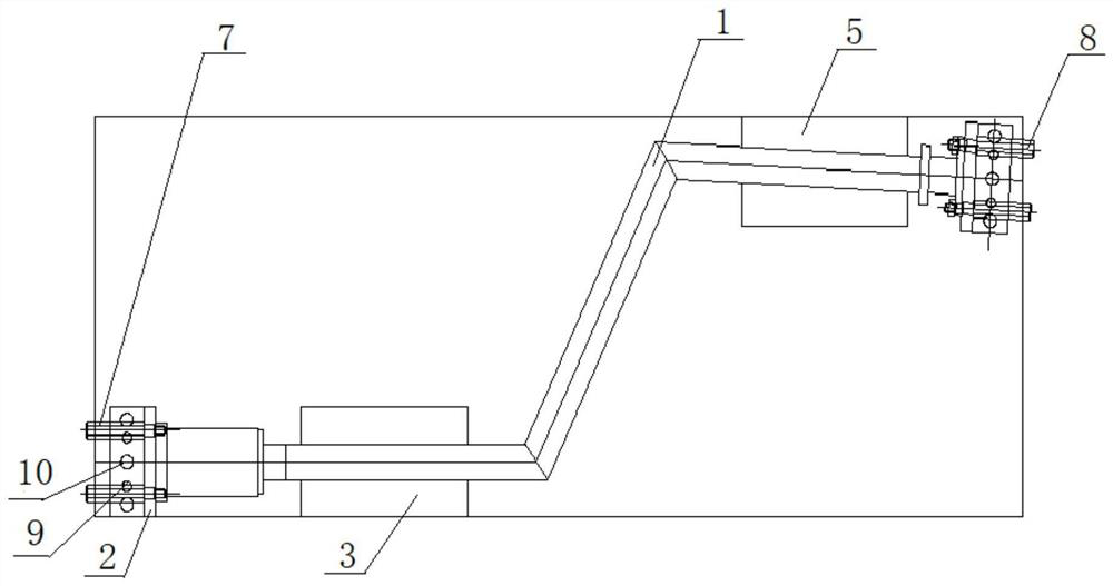
[0035] figure 1 and figure 2 Respectively, the front view and top view of the thin-wall special-shaped tie rod rapid positioning welding device according to the embodiment of the present invention, combined with figure 1 and figure 2 , the thin-wall special-shaped pull rod rapid positioning welding device of the present invention includes a first end positioning block 2, an inclined plane p...


PUM


Abstract

The invention discloses a rapid positioning and welding device for a thin-wall special-shaped pull rod. The rapid positioning and welding device comprises a positioning bottom plate, an end positioning block, a slope positioning block and a plane positioning block, the slope positioning block and the plane positioning block are located below the thin-wall special-shaped pull rod and used for supporting and fixing the middle of the thin-wall special-shaped pull rod; and the end positioning block comprises a first end positioning block and a second end positioning block which are located at thetwo longitudinal ends of the positioning bottom plate respectively and used for positioning the two ends of the thin-wall special-shaped pull rod, and the relative positions of flanges to be welded and the thin-wall special-shaped pull rod can be adjusted through angle setting of the end positioning block. The invention further discloses a forming method of the rapid positioning and welding devicefor the thin-wall special-shaped pull rod and a welding method applying the rapid positioning and welding device for the thin-wall special-shaped pull rod. According to the rapid positioning and welding device, the thin-wall special-shaped pull rod and the flanges at the two ends can be rapidly positioned and welded, and the requirement for flange welding of the thin-wall special-shaped pull rodis met.

Description

technical field [0001] The invention belongs to the technical field of manufacturing thin-wall special-shaped tie rods for automobiles and other types of motor vehicles, and in particular relates to a fast positioning welding device for thin-wall special-shaped tie rods used in shift control devices of automobile transmissions, and its forming and welding methods. Background technique [0002] As an important part of the shift control device of the automobile transmission, the tie rod is connected with the ball pin and the universal joint to transmit the tension of the transmission preselection valve. Its shape and structure are generally straight pull rods, and the two ends are welded with the transmission flange. [0003] The tie rod on the automobile transmission is mainly welded by steel pipe and flange. After the steel pipe is blanked, the two ends are welded together with the flange. The general processing method is roughly as follows: 1) Purchase the steel pipe dire...

Claims


Application Information

Patent Timeline
Patent Type & Authority Applications(China)
IPC IPC(8): B23K9/32B23K9/173B23K37/053
CPCB23K9/173B23K9/32B23K37/0536
Inventor 张谢民邓平盛贺仁凤刘远张小玲李新国张彬
Owner HUBEI SANJIANG AEROSPACE WANFENG TECH DEV
Learn More