Multi-angle synchronous efficient grinding equipment for automobile brake disc

A vehicle braking, multi-angle technology, applied in grinding/polishing equipment, metal processing equipment, grinding machines, etc., can solve the problems of easy production of defective products, low processing accuracy, low work efficiency, etc., to improve economic efficiency, avoid The effect of repositioning and improving work efficiency

Active Publication Date: 2020-12-04
浙江杭万汽车零部件实业有限公司
View PDF7 Cites 38 Cited by
  • Summary
  • Abstract
  • Description
  • Claims
  • Application Information

AI Technical Summary

Problems solved by technology

[0005] In order to solve the above technical problems, a multi-angle synchronous high-efficiency grinding equipment for automobile brake discs is provided. This technical solution solves the need to perform grinding operations on the outer surface of the brake disc during the production and processing of the brake disc. After the moving disc is manually positioned, the surface of the brake disc is polished with a hand-held grinding device. This method requires manual positioning and grinding of the brake disc. The operator has high work intensity, low work efficiency, and low processing accuracy, which is prone to Defective products affect the performance of the brake disc; some drilling equipment is used to automatically polish the surface of the brake disc, but the existing grinding equipment cannot perform synchronous grinding operations on the side wall and top surface of the brake disc, resulting in grinding The steps are cumbersome and the work efficiency is low

Method used


Image

  • Multi-angle synchronous efficient grinding equipment for automobile brake disc
  • Multi-angle synchronous efficient grinding equipment for automobile brake disc
  • Multi-angle synchronous efficient grinding equipment for automobile brake disc

Examples


Embodiment Construction

[0034] The following description serves to disclose the present invention to enable those skilled in the art to carry out the present invention. The preferred embodiments described below are only examples, and those skilled in the art can devise other obvious variations.

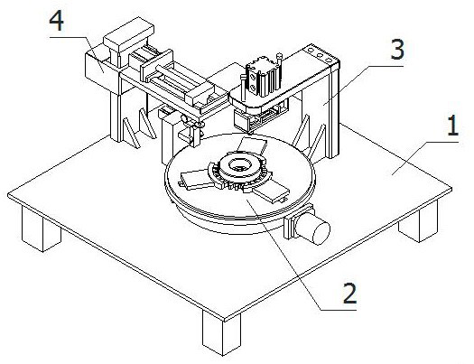
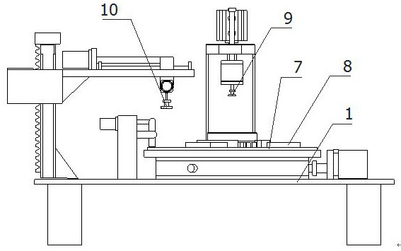
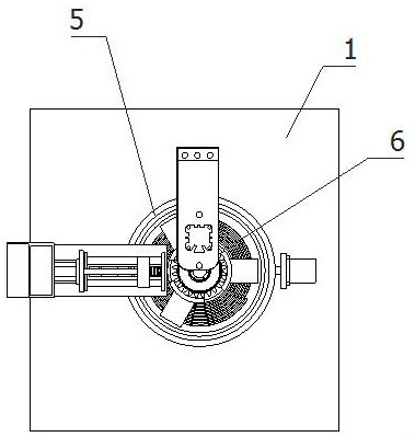
[0035] refer to Figure 1-Figure 3 The multi-angle synchronous high-efficiency grinding equipment for automobile brake discs shown includes a loading manipulator and an unloading manipulator, as well as a processing platform 1, a clamping and rotating assembly 2, a top surface grinding assembly 3 and side wall chamfering Grinding assembly 4, clamping and rotating assembly 2 is horizontally and fixedly installed at the top center of processing platform 1, top surface grinding assembly 3 and side wall chamfering grinding assembly 4 are fixedly installed on the top of processing platform 1 respectively, top surface grinding assembly 3 and side The wall chamfering and grinding components 4 are respectively loca...


PUM


Abstract

The invention relates to the technical field of automobile brake disc grinding machining, in particular to multi-angle synchronous efficient grinding equipment for an automobile brake disc. The equipment further comprises a machining platform, a clamping rotating assembly, a top surface grinding assembly and a side wall chamfering and grinding assembly, wherein the clamping rotating assembly comprises a mounting disc, a transmission disc, a positioning disc, a clamping jaw and a pressing mechanism; the top surface grinding assembly comprises a first lifting mechanism, a first horizontal displacement mechanism and a top end horizontal grinding mechanism, and the top end horizontal grinding mechanism comprises a horizontal grinding disc capable of grinding the top surface of the automobile brake disc; and the side wall chamfering and grinding assembly comprises a second lifting mechanism, a second horizontal displacement mechanism, an angle adjusting mechanism and a side wall chamferingand grinding mechanism, and the side wall chamfering and grinding mechanism comprises a side wall grinding disc. The equipment shown can precisely and efficiently position and clamp the automobile brake disc, and the surface, the side wall and the edge of the brake disc are synchronously and accurately ground, such that the working efficiency is greatly improved, and repositioning is avoided.

Description

technical field [0001] The invention relates to the technical field of grinding and processing of automobile brake discs, in particular to multi-angle synchronous high-efficiency grinding equipment for automobile brake discs. Background technique [0002] The brake is a component in the braking system that is used to generate braking force that hinders the movement or movement tendency of the vehicle. Except for various slowing devices, automobile brakes are almost all friction brakes that use the friction between the fixed element and the working surface of the rotating element to generate braking torque. At present, the friction brakes widely used in various types of vehicles can be divided into two categories: drum type and disc type according to the different rotating elements. The difference between them is: the rotating element in the friction pair of drum brake is a brake drum, with its cylindrical surface as the working surface; the rotating element in the friction ...

Claims


Application Information

Patent Timeline
Patent Type & Authority Applications(China)
IPC IPC(8): B24B5/36B24B41/06B24B47/06B24B27/00B24B41/00
CPCB24B5/36B24B27/0023B24B27/0069B24B41/005B24B41/06B24B47/06
Inventor 付永生
Owner 浙江杭万汽车零部件实业有限公司
Why Eureka
Try Eureka