A textile yarn winding device

A winding device and textile yarn technology, which is applied in the directions of transportation and packaging, thin material handling, and delivery of filamentous materials, etc. It can solve the time-consuming and labor-consuming installation and removal of the winding roller and affect the winding efficiency of the winding device and other problems, to achieve the effect of increasing the fixed effect, reducing the circular jump, and increasing the transmission efficiency

Active Publication Date: 2022-04-22
宿州玥加服装有限公司
View PDF8 Cites 0 Cited by
  • Summary
  • Abstract
  • Description
  • Claims
  • Application Information

AI Technical Summary

Problems solved by technology

[0005] In order to make up for the deficiencies of the existing technology, the winding roller is set on the rotating shaft, and then the winding roller is fastened through the clamping plate and the screw thread of the rotating shaft to ensure that the winding roller rotates with the rotating shaft and Rewinding textile yarn, but the clamping plate needs to rotate more times to lock the rewinding roller, resulting in time-consuming and labor-consuming installation and disassembly of the rewinding roller, which affects the rewinding efficiency of the rewinding device. The present invention proposes A textile yarn winding device

Method used


Image

  • A textile yarn winding device
  • A textile yarn winding device
  • A textile yarn winding device

Examples


Embodiment approach

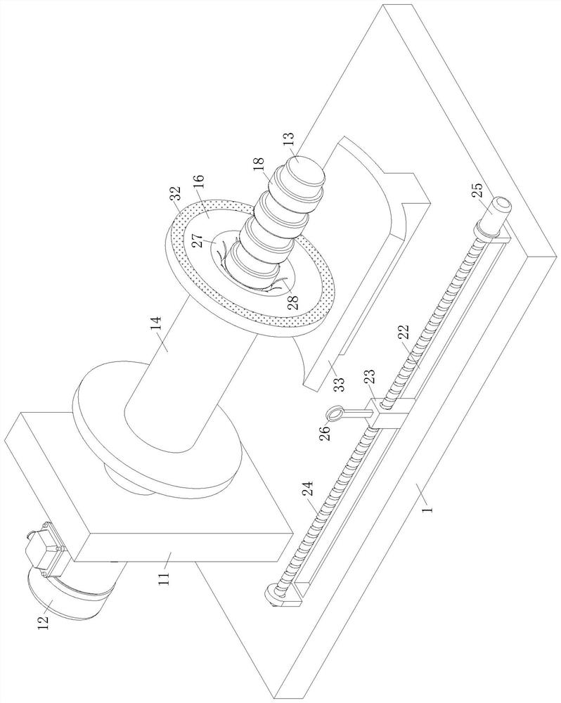
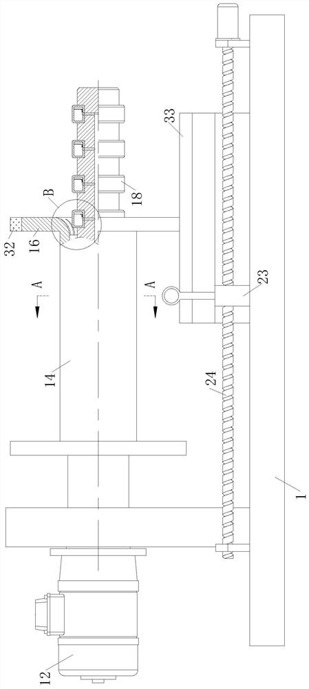
[0024] As an embodiment of the present invention, the end of the No. 1 hole 15 close to the elastic ring 18 is provided with an arc-shaped chamfer 27, and a set of friction grooves 28 are evenly distributed on the inner circumference of the chamfer 27, and the chamfer 27 cooperates with friction The groove 28 reduces the wear of the elastic ring 18 and prolongs the service life of the elastic ring 18; through the arc-shaped chamfer 27, the extrusion of the edge of the first hole 15 on the elastic ring 18 is reduced, thereby further reducing the excessive bending of the elastic ring 18 Deformation increases the service life of the elastic ring 18, and the chamfer 27 cooperates with the friction groove 28, so that the elastic ring 18 expands and embeds in the friction groove 28, thereby increasing the friction between the elastic ring 18 and the winding roller 14, and reducing the elastic ring 18 The wear caused by relative sliding with the winding roller 14 increases the rotatio...


PUM


Abstract

The invention belongs to the field of textile technology, and specifically relates to a textile yarn winding device, which includes a base; the top of the base is fixedly connected to a No. 1 motor through a support; There is a winding roller, and the rotating shaft runs through the No. 1 hole in the middle of the winding roller; the end of the rotating shaft away from the support is provided with a set of annular limiting grooves, and a hollow elastic ring is set in the limiting grooves; the middle of the rotating shaft is along the axial direction There is a No. 2 hole; the bottom of the limit groove is provided with a No. 3 hole that is respectively connected to the elastic ring and the No. Screw; both ends of the screw are rotationally connected with the bracket fixed to the base, and the screw is driven by the No. 2 motor fixed on the bracket; the top of the slider is fixedly connected with a lead ring through the support rod; the invention quickly fixes and rewinds through the expansion of the elastic ring Roller, to further increase the disassembly and assembly efficiency of the winding roller.

Description

technical field [0001] The invention belongs to the technical field of textiles, in particular to a textile yarn winding device. Background technique [0002] Textile is the general term for spinning and weaving. Ancient Chinese textile and printing and dyeing technology has a very long history. As early as in the primitive society, in order to adapt to climate change, the ancients knew how to use local materials and use natural resources as the basis for textile, printing and dyeing. Raw materials, as well as the manufacture of simple textile tools, until today, our daily clothes, some daily necessities and artworks are all products of textile and printing and dyeing technology, and yarn winding devices are needed in textile production. After retrieval, The patent document with the authorized notification number CN207329969U discloses a yarn winding device for textile machines, including a base, a double-axis motor is arranged on the upper end surface of the base, and a lef...

Claims


Application Information

Patent Timeline
Patent Type & Authority Patents(China)
IPC IPC(8): B65H54/28B65H75/14B65H75/24
CPCB65H54/2818B65H75/14B65H75/243B65H2701/31
Inventor 林胜男李浩
Owner 宿州玥加服装有限公司
Why Eureka
Try Eureka