Positioning lock device

A technology for positioning locks and dead bolts, which can be used in washing devices, other washing machines, textiles and papermaking, etc., and can solve problems such as small damping force

Pending Publication Date: 2020-12-04
HANGZHOU KAMBAYASHI ELECTRONICS
View PDF0 Cites 0 Cited by
  • Summary
  • Abstract
  • Description
  • Claims
  • Application Information

AI Technical Summary

Problems solved by technology

[0002] In recent years, top-loading drum washing machines have been introduced on the market, which is convenient for placing and taking out clothes. However, in the side-loading drum washing machine, there is no need for positioning and locking the inner drum, but it becomes a problem in the top-loading drum washing machine. The door of the inner drum does not necessarily face up, so it is often necessary to manually turn it in place, and hold the inner drum with hands to prevent rotation, so that it is convenient to take and place clothes. The existing technology uses the inherent damping of the inner drum and the motor for positioning, and its damping force is relatively strong Small, can rotate and shift if laundry is off center

Method used


Image

  • Positioning lock device
  • Positioning lock device
  • Positioning lock device

Examples


Embodiment Construction

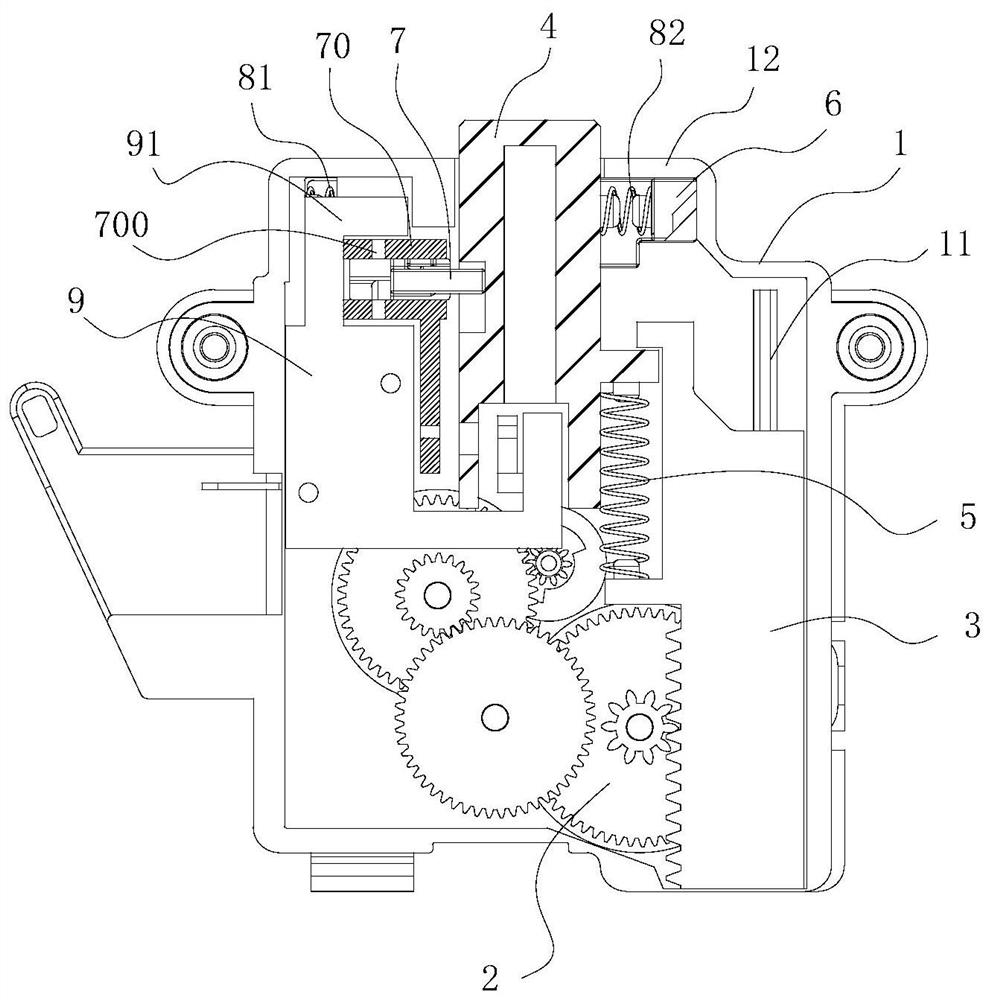
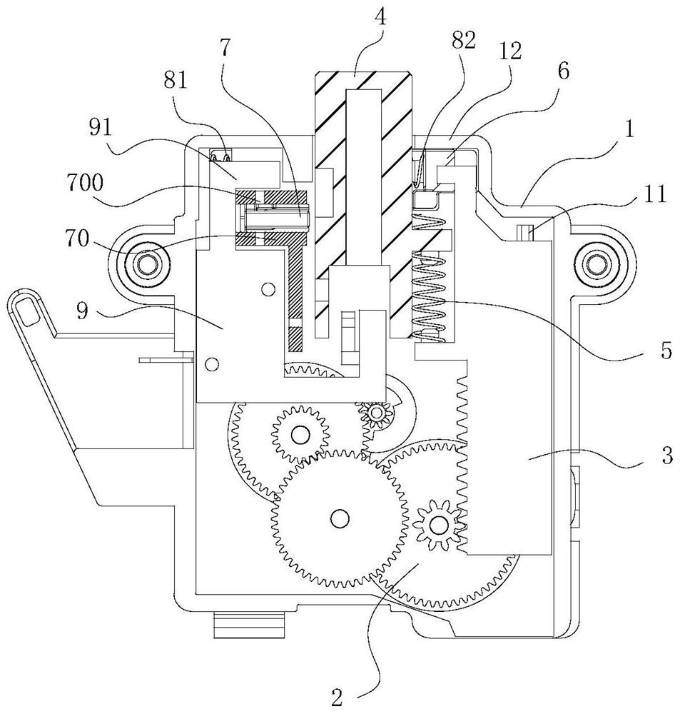
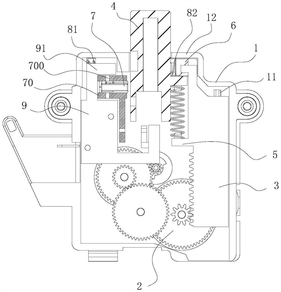
[0020] refer to Figure 1 to Figure 5 , a positioning lock device of the present invention, comprising a housing 1, a gear set 2 disposed in the housing 1, a rack assembly 3, a deadbolt 4, a first spring 5, a deadbolt locking assembly and a signal control assembly 9, the The gear set 2 is driven by a motor, the gear set 2 is provided with a driving gear, and the driving gear is engaged with the rack assembly 3 for driving the rack assembly 3 to move vertically. One side is provided with dead bolt 4, and described rack assembly 3 is connected with dead bolt 4 by first spring 5, and the top of described housing 1 is provided with the outlet that is passed through for dead bolt 4, and one side of described outlet is provided with There is a limit stop wall 12 for blocking the rack assembly 3, one side of the dead bolt 4 is provided with a dead bolt locking assembly and a signal control assembly 9, and the locking bolt locking assembly is driven by the rack assembly 3 in a horizon...


PUM


Abstract

The invention provides a positioning lock device. The device comprises a shell, a gear set, a rack assembly, a spring bolt, a first spring, a spring bolt locking assembly and a signal control assembly, wherein the gear set, the rack assembly, the spring bolt, the first spring, the spring bolt locking assembly and the signal control assembly are mounted in the shell. The gear set is driven by a motor, a driving gear is arranged on the gear set, the driving gear is meshed with the rack assembly, and used for driving the rack assembly to move in the vertical direction, the spring bolt is arrangedat one side of the rack assembly, the rack assembly is connected with the spring bolt through the first spring, an outlet allowing the spring bolt to penetrate out is formed at the top of the shell,and the spring bolt locking assembly and the signal control assembly are arranged at one side of the spring bolt. The spring bolt locking assembly is driven by the rack assembly to move in the horizontal direction, a locking groove is formed at one side of the spring bolt, the spring bolt locking assembly is used for switching the output state of the signal control assembly, the positioning lock device can more accurately position and lock an inner barrel of a roller washing machine, and it is guaranteed that when the roller washing machine is stopped and clothes are taken and placed, a door of the inner barrel is in an upward state.

Description

【Technical field】 [0001] The invention relates to the technical field of washing equipment, in particular to a positioning lock device. 【Background technique】 [0002] In recent years, top-loading drum washing machines have been introduced on the market, which is convenient for placing and taking out clothes. However, in the side-loading drum washing machine, there is no need for positioning and locking the inner drum, but it becomes a problem in the top-loading drum washing machine. The door of the inner drum does not necessarily face up, so it is often necessary to manually turn it in place, and hold the inner drum with hands to prevent rotation, so that it is convenient to take and place clothes. The existing technology uses the inherent damping of the inner drum and the motor for positioning, and its damping force is relatively strong Small, it will rotate and shift if the clothes are off-center. 【Content of invention】 [0003] The purpose of the present invention is ...

Claims


Application Information

Patent Timeline
Patent Type & Authority Applications(China)
IPC IPC(8): D06F37/00
CPCD06F37/00
Inventor 竺建军何凯
Owner HANGZHOU KAMBAYASHI ELECTRONICS
Why Eureka
Try Eureka