
Machine tool, sensor module, and measuring method

A technology of sensor components and measurement methods, applied in the direction of measuring devices, measuring/indicating equipment, metal processing machinery parts, etc., can solve the problems of arm obstacles, inability to install arms, and difficulty in miniaturization of turret lathes, etc.

Inactive Publication Date: 2012-09-05
MURATA MASCH LTD
View PDF1 Cites 0 Cited by
  • Summary
  • Abstract
  • Description
  • Claims
  • Application Information

AI Technical Summary

Problems solved by technology

[0034] However, according to the prior art, the arm for attaching the sensor and the turret tool post are provided separately, so it is difficult to miniaturize the turret lathe
[0035] In addition, if Figure 24 (A) and Figure 24 As shown in (B), the radius of rotation of the arm is large, so it may not be possible to install the arm
[0036] Furthermore, since the arm is provided in front of the turret tool post, the arm is likely to become an obstacle when exchanging tools

Method used


Image

  • Machine tool, sensor module, and measuring method
  • Machine tool, sensor module, and measuring method
  • Machine tool, sensor module, and measuring method

Examples


Embodiment approach 1

[0082] A turret lathe as an example of a machine tool in Embodiment 1 of the present invention will be described in detail with reference to the drawings.

[0083] First, use Figure 1 ~ Figure 3 The configuration of the turret lathe according to Embodiment 1 will be described.

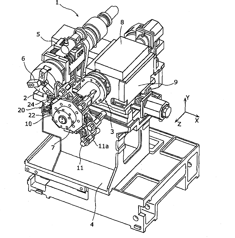
[0084] figure 1 It is a perspective view showing the appearance of the turret lathe according to Embodiment 1 of the present invention.

[0085] like figure 1 Shown, the basic composition of turret lathe 1 and Figure 21 The shown conventional general turret lathe 200 is similarly equipped with a spindle 2 for gripping and rotating a workpiece, a turret 3 which is a rotary tool selection mechanism, and the like.

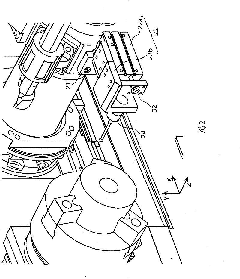
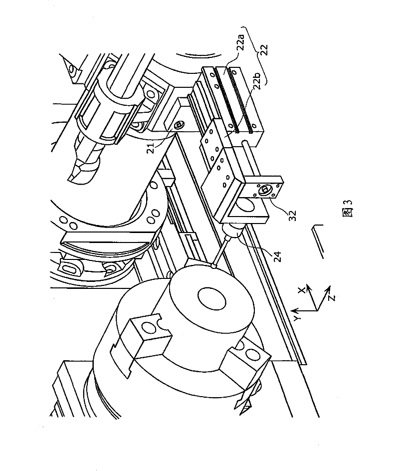
[0086] However, the turret lathe 1 further includes a sensor unit 20 as a characteristic component.

[0087] The sensor unit 20 has a support 22 that expands and contracts in the radial direction of the turret 7 and a sensor 24 for measuring the dimensions of the workpiece, and is capa...

Embodiment approach 2

[0157] As Embodiment 2 of the present invention, a turret lathe 100 having a sensor unit 120 capable of expanding and contracting a sensor distance by turning an arm 122 provided with a sensor 24 at an end will be described. The turret lathe 100 is another example of the machine tool of the present invention.

[0158] In addition, the basic configuration of the turret lathe 100 of the second embodiment is the same as that of the turret lathe 1 of the first embodiment. Therefore, in Embodiment 2, the description will be centered on the sensor unit 120 as a characteristic component.

[0159] First, use Figure 8 ~ Figure 11 , the basic configuration of the sensor unit 120 in the second embodiment will be described.

[0160] Figure 8 It is an enlarged perspective view showing the appearance of the sensor unit 120 in Embodiment 2 of the present invention.

[0161] The sensor unit 120 has: a base 121, a rotating arm 122 mounted on the base 121, a gear box 123 integrally rotating...


PUM


Abstract

The present invention provides a machine tool for executing measurement in machine for workpiece size and for correctly measuring diameter of the workpiece, the machine tool can be minimized. The invention is a machine tool (1) for machining a workpiece held by a spindle (2), comprising: a turret tool post (7) having tool holding faces (10); a sensor (24) for measuring dimensions of the workpiece; and a support strut (22) which is mounted on one of the tool holding faces (10), holds the sensor (24) and extends and shortens a sensor distance which is a distance between the one of the tool holding faces and the sensor in a radial direction of the turret tool post (7), wherein, while the sensor distance is shortened, a length of the support strut (22) in the radial direction is such that thesupport strut and the sensor (24) do not interfere with another structural element of the machine tool (1) when the turret tool post (7) rotates.

Description

technical field [0001] The present invention relates to a machine tool for metal processing with a tool mounted on a turret, and in particular to a technique for measuring the size of a workpiece, which is an object to be processed. Background technique [0002] Conventionally, as one of machine tools, a turret lathe provided with a rotary table that is a rotary tool selection mechanism has been used. [0003] Figure 21 It is an external perspective view showing an example of a general conventional turret lathe. like Figure 21 As shown, the turret lathe 200 includes the spindle 2 and the turret 3 . [0004] The spindle 2 is supported by a headstock 5 provided on the table 4, and a workpiece (not shown) is held and rotated by a spindle chuck 6 . [0005] The turntable 3 is composed of a turret tool rest 7 , an indexing mechanism 8 and a turret slide 9 . [0006] The turret tool post 7 has a plurality of tool mounting surfaces 10 around the rotation axis, and is rotatably...

Claims


Application Information

Patent Timeline
Patent Type & Authority Patents(China)
IPC IPC(8): B23B3/00B23B25/06B23Q17/20G01B21/00
CPCB23Q17/20B23B25/06B23Q11/08Y10T29/5165B23B3/16B23B7/04G05B19/401
Inventor 田中诚
Owner MURATA MASCH LTD
Learn More