
A method for identifying low-permeability gas-water layers while drilling

A water layer and gas seepage technology, which is applied in earthwork drilling, measurement, borehole/well components, etc., can solve the problems of low coincidence rate of gas logging interpretation, low porosity and inaccuracy of tight gas reservoirs, and improve interpretation The effect of coincidence rate, wide application range and accurate interpretation

Active Publication Date: 2021-11-02
CNPC BOHAI DRILLING ENG +1
View PDF7 Cites 0 Cited by
  • Summary
  • Abstract
  • Description
  • Claims
  • Application Information

AI Technical Summary

Problems solved by technology

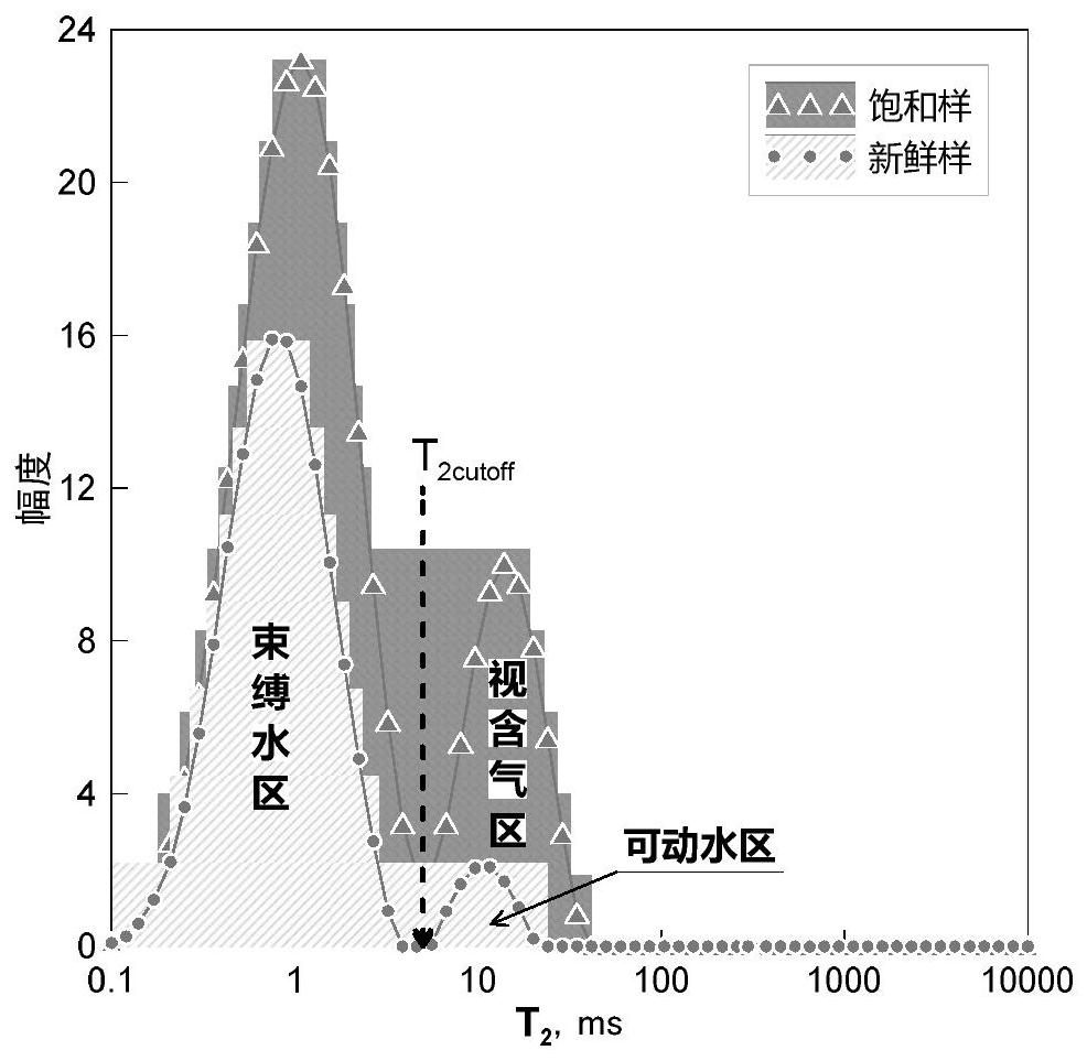
[0002] Tight gas reservoirs are characterized by low porosity, low permeability, low abundance, and complex gas-water relationship. The identification while drilling mainly relies on gas logging technology. Since the gas logging data is greatly affected by drilling conditions, it is difficult to identify formations. Water content and reservoir effectiveness lead to a low coincidence rate of gas logging interpretation; nuclear magnetic resonance logging technology can effectively identify the water content and availability of reservoirs, but because the measurement is carried out under normal temperature and pressure conditions on the surface, the gas The number of hydrogen-containing molecules is low, and no gas-containing signal can be detected by NMR; mud logging evaluation personnel compare the saturated sample with the fresh sample T 2 The amplitude difference between the spectra is defined as the gas-bearing area. This assumption lacks scientific basis, because the gas has strong compressibility, even if there is gas in the pores, it is impossible to know the gas-bearing abundance; On the premise of the number of hydrogen molecules or gas fullness, it is also inaccurate to evaluate the gas saturation

Method used


Image

  • A method for identifying low-permeability gas-water layers while drilling
  • A method for identifying low-permeability gas-water layers while drilling
  • A method for identifying low-permeability gas-water layers while drilling

Examples


Embodiment Construction

[0032] In the following description, numerous specific details are given in order to provide a more thorough understanding of the present invention. It will be apparent, however, to one skilled in the art that embodiments of the invention may be practiced without one or more of these details. In other examples, some technical features known in the art are not described in order to avoid confusion with the embodiments of the present invention.

[0033] In order to thoroughly understand the embodiments of the present invention, a detailed structure will be set forth in the following description. It is evident that practice of the embodiments of the invention is not limited to specific details familiar to those skilled in the art. Preferred embodiments of the present invention are described in detail below, however, the present invention may have other embodiments besides these detailed descriptions.

[0034] Embodiments of the present invention are described in further detail ...


PUM


Abstract

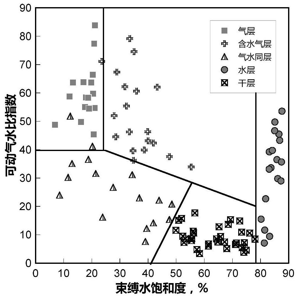
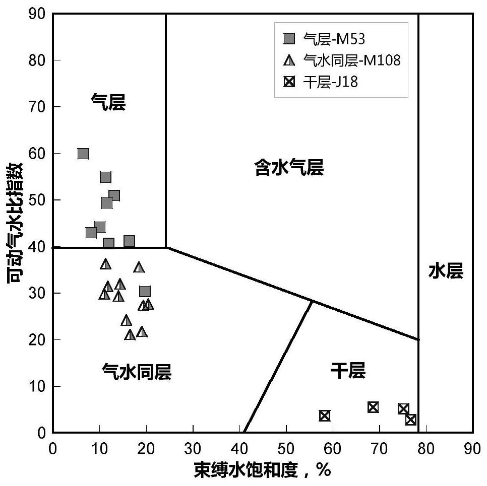
The invention discloses a method for identifying a low-permeability gas water layer while drilling. The steps are: S1, calculating the movable gas saturation; S2, determining the T of formation water 2 Cutoff value, calculate the movable water saturation and irreducible water saturation; S3, calculate the movable air-water ratio index; S4, take the movable air-water ratio index as the ordinate, and the irreducible water saturation as the abscissa, establish an explanation chart; S5 1. Project the irreducible water saturation and the movable air-water ratio index of the layer to be explained onto the interpretation chart, and perform interpretation according to the interpretation area where the landing point is located. The method of the invention effectively solves the difficult problem of identifying tight gas reservoirs while drilling, and has the advantages of simple operation, low cost, accurate interpretation and wide application prospect.

Description

technical field [0001] The invention relates to the technical field of interpretation and evaluation of oil and gas layers, in particular to a method for identifying low-permeability gas water layers while drilling. Background technique [0002] Tight gas reservoirs are characterized by low porosity, low permeability, low abundance, and complex gas-water relationship. The identification while drilling mainly relies on gas logging technology. Since the gas logging data is greatly affected by drilling conditions, it is difficult to identify formations. Water content and reservoir effectiveness lead to a low coincidence rate of gas logging interpretation; nuclear magnetic resonance logging technology can effectively identify the water content and availability of reservoirs, but because the measurement is carried out under normal temperature and pressure conditions on the surface, the gas The number of hydrogen-containing molecules is low, and no gas-containing signal can be det...

Claims


Application Information

Patent Timeline
Patent Type & Authority Patents(China)
IPC IPC(8): E21B47/12E21B49/00
CPCE21B47/12E21B49/00
Inventor 孙红华姜维寨于海军范伟孟庆峰王金友宋义民李毅逵戴广阔张明扬胡洋乔德民张亚宾王灿丹婷徐婕陈永红侯玉花陈玉蓉
Owner CNPC BOHAI DRILLING ENG
Learn More