Standard trajectory tracking guidance method based on height-range ratio

A standard trajectory and range technology, applied in the direction of vehicle position/route/height control, control/regulation system, non-electric variable control, etc., to achieve the effect of simple form, small amount of calculation, and improved guidance accuracy

Active Publication Date: 2020-12-04
HARBIN INST OF TECH
View PDF12 Cites 3 Cited by
  • Summary
  • Abstract
  • Description
  • Claims
  • Application Information

AI Technical Summary

Problems solved by technology

[0004] In order to solve the standard trajectory tracking problem for the underactuated reentry vehicle system, the present invention combines the longitudinal plane and the lateral plane, and proposes a standard tra...

Method used


Image

  • Standard trajectory tracking guidance method based on height-range ratio
  • Standard trajectory tracking guidance method based on height-range ratio
  • Standard trajectory tracking guidance method based on height-range ratio

Examples


Embodiment 1

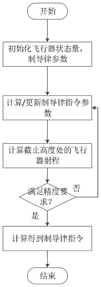
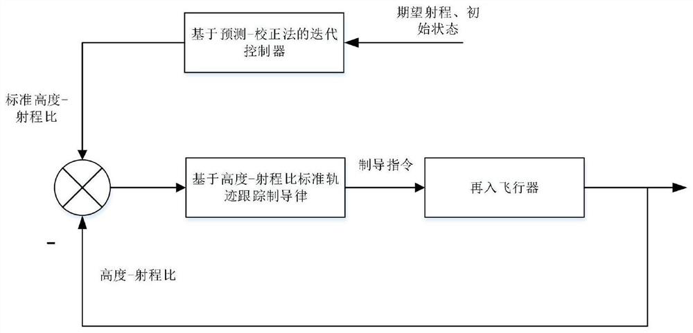
[0032] A standard trajectory tracking guidance method based on altitude-to-range ratio, said method comprising the steps of:

[0033] Step 1: According to the initial state of the aircraft and the final desired state (including speed and position), determine the total range of the aircraft, and obtain the altitude-velocity corridor of the aircraft under the constraint conditions ( re-entry corridor);

[0034]

[0035]

[0036] Among them, n max In order to allow the maximum overload; m T is the mass of the aircraft; S is the characteristic area of ​​the aircraft; C y is the aerodynamic coefficient; q max is the allowable maximum dynamic pressure; ρ is the atmospheric density;

[0037] Since both the atmospheric density and the aerodynamic coefficient in the above formula can be described as a function of height, the maximum velocity at different heights can be calculated according to the above formula, and the upper boundary v of the re-entry corridor can be obtained...

Embodiment 2

[0065] Such as: the standard trajectory tracking guidance method under the condition that there is uncertainty in the aerodynamic environment of the variable center of mass reentry vehicle, the method includes the following steps:

[0066] Step 1: According to the initial state of the aircraft and the final desired state (including speed and position), determine the total range of the aircraft, and obtain the altitude-velocity corridor of the aircraft under the constraint conditions ( re-entry corridor);

[0067]

[0068]

[0069] Among them, n max In order to allow the maximum overload; m T is the mass of the aircraft; S is the characteristic area of ​​the aircraft; C y is the aerodynamic coefficient; q max is the allowable maximum dynamic pressure; ρ is the atmospheric density;

[0070] Since both the atmospheric density and the aerodynamic coefficient in the above formula can be described as a function of height, the maximum velocity at different heights can be ca...


PUM


Abstract

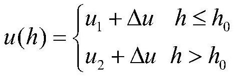
The invention discloses a standard trajectory tracking guidance method based on a height-range ratio. The method comprises the steps of 1, determining the total range of an aircraft and an aircraft height and speed corridor under constraint conditions; 2, designing a guidance law instruction of a segmentation constant value, and recording the guidance law instruction as u (h); 3, obtaining terminal ranges f1 and f2 in a prediction correction method formula; 4, calculating a gain k, a parameter h *, a range f *, and an updating parameter tau on the premise of an approximate linearization hypothesis, ; 5, carrying out n times of iterative computation to obtain a time sequence of theheight-range ratio; 6, when the reentry vehicle is subjected to external interference in the flight process, and the initial condition is uncertain, improving the guidance precision through the correction value delta u of the control quantity; and 7, forming a guidance law instruction form when the reentry vehicle is subjected to external interference and initial conditions are uncertain. In order to solve the problem of standard trajectory tracking of an under-actuated reentry vehicle system, longitudinaland lateral planes are combined, and the concept of height-range ratio is introduced to solve the problem.

Description

technical field [0001] The invention belongs to the technical field of aircraft navigation, guidance and control; in particular, it relates to a standard trajectory tracking guidance method based on altitude-range ratio. Background technique [0002] Due to the influence of aerodynamic perturbation and wind interference on the reentry aircraft during flight, it will have a corresponding impact on its flight state; The guidance law design of the aircraft is particularly important; the standard trajectory method is one of the commonly used guidance methods, and the correction value of the control quantity is obtained by comparing with the state quantity in the standard trajectory, thereby improving the guidance accuracy. [0003] However, during the actual flight of the aircraft, the aircraft may be under-actuated due to actuator limitations or failures. For the under-actuated re-entry aircraft system, the traditional standard trajectory tracking method is difficult to satisfy...

Claims


Application Information

Patent Timeline
IPC IPC(8): G05D1/10
CPCG05D1/101
Inventor 晁涛李冠林王松艳杨明
Owner HARBIN INST OF TECH
Why Eureka
Try Eureka