
Multi-step decision-making method for planning trajectory around multiple no-fly zones

A no-fly zone and ballistic technology, applied in the field of multi-step decision-making ballistic planning, can solve problems such as increasing the energy consumption of missiles, easily causing overload oscillation, and destroying the boundary constraints of the no-fly zone.

Active Publication Date: 2018-01-23
BEIHANG UNIV
View PDF6 Cites 8 Cited by
  • Summary
  • Abstract
  • Description
  • Claims
  • Application Information

AI Technical Summary

Problems solved by technology

The optimal control method converts the constraint conditions of the no-fly zone into a penalty item and adds it to the performance index function, so that the analytical solution of the penetration command around multiple no-fly zones can be deduced, but it is only suitable for a small number of no-fly due to the complicated derivation process The derivation of command analytical solutions obtained by the potential energy method is relatively simple, but it is difficult to select the guidance coefficient and it is not easy to obtain a smooth trajectory, especially at the boundary of the no-fly zone, it is easy to cause overload oscillation, thereby destroying the boundary constraints of the no-fly zone , which will also increase the energy consumption of the missile

Method used


Image

  • Multi-step decision-making method for planning trajectory around multiple no-fly zones
  • Multi-step decision-making method for planning trajectory around multiple no-fly zones
  • Multi-step decision-making method for planning trajectory around multiple no-fly zones

Examples


Embodiment 1

[0146] Embodiment 1 verifies the simulation effect of the single no-fly evasion guidance law of the present invention under different maximum available overload conditions.

[0147] Step 5: Design of trajectory planning method around multiple no-fly zones based on multi-step decision theory

[0148] In order to facilitate the design of the trajectory planning method of the present invention, a multi-step decision-making model is introduced as follows:

[0149] Define 1Γ-step decision model (S, D, T, J), where

[0150] 1) Record H:={0,1,2,...,Γ}, where Γ represents the number of decision-making steps;

[0151] 2) State space S is a non-empty set whose elements are all state variables s(s∈S). Denote S(k) as the state set at the starting point of the kth step, where k∈H;

[0152] 3) D(k,s) is the set of all feasible decisions starting from the state variable s in the kth step. The decision space D is the total set of feasible decisions of all decision steps;

[0153] 4) In t...

Embodiment

[0176] Embodiment one

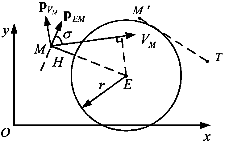
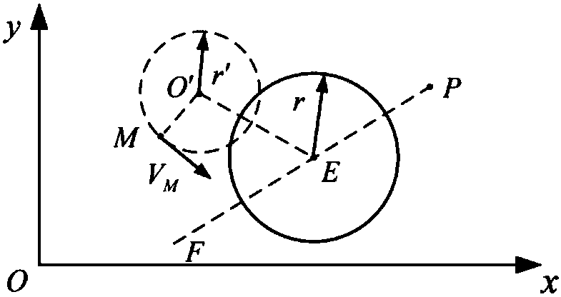
[0177] This embodiment considers the case of a single no-fly zone constraint to verify the penetration performance of the OBPCG guidance law of the present invention under different maximum available overload limits. The target position is fixed XT=(30,30)km, the initial position of the missile is XM=(-60,0)km, and the initial velocity is No-fly zone radius r E = 30km. Figure 10 It shows the flight trajectory of the OBPCG guidance law of the present invention when the maximum available overload is 10G, 6G, and 3G respectively. It can be seen that when the maximum available overload is large enough, OBPCG will control the missile to bypass the no-fly along a shorter flight path However, when the maximum available overload is small, since the minimum turning radius of the missile is greater than the distance from the missile to the boundary of the no-fly zone, OBPCG will control the missile to bypass the no-fly zone along a longer flight path, so as t...

Embodiment 2

[0179] This embodiment verifies the performance of the multi-step decision-making trajectory planning method of the present invention in the case of arbitrary arrangement of multiple no-fly zones. The 15 no-fly zones are randomly distributed, and the radius of the no-fly zone varies from 15km to 36km. The initial state of the missile is XM=(60,0)km, The initial state of the target is XT 0 =(-170,-230)km, VT 0 =(-130,150)m / s. Assume that the target maneuvers according to the following trajectory

[0180]

[0181] Among them, A=300km, T=70km.

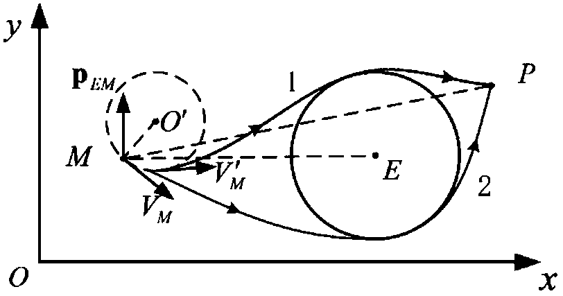
[0182] Figure 11 The ballistic trajectory of the multi-step decision-making trajectory planning method of the present invention under the constraints of multiple no-fly zones is shown. It can be seen that under the action of the trajectory planning method of the present invention, the missile completes the multi-no-fly zone along a relatively smooth and short trajectory. Fly zone penetration missions, and strictly ensure the b...


PUM


Abstract

The invention relates to a multi-step decision-making method for planning a trajectory around multiple no-fly zones. The method comprises the following steps of 1 impact point prediction calculation,2 boundary constraint handling scheme, 3 orientation adjustment scheme, 4 proportional navigation and 5 implementation of the method for planning the trajectory around multiple no-fly zones on the basis of a multi-step decision-making theory. Compared with an off-line planning method, the trajectory planning method has the advantages that the real-time performance is high, the on-line planning speed is high, and new avoiding instructions can be generated in real time according to the task and battlefield environment requirements; and compared with a traditional on-line planning method, the trajectory planning method has the advantages that the derivation process is simple, the condition of a large amount of randomly-distributed no-fly zones can be processed, and the trajectory planning method has the higher adaptability. According to the trajectory planning method, boundary constraints of the no-fly zones can be strictly guaranteed, a flying trajectory is smooth, the required overloadis small, and the trajectory planning method has the higher guidance precision.

Description

technical field [0001] The invention relates to a multi-step decision-making trajectory planning method around multiple no-fly zones, belonging to the fields of aerospace technology, weapon technology, and guidance control. Background technique [0002] With the development of the missile defense system, the perfect three-dimensional land, sea and air missile defense system has formed an all-round and multi-level protection for important military targets, posing a serious threat to modern missile penetration. Therefore, in order to effectively attack targets located in or behind the defense zone, it is necessary to avoid the enemy's detection radar and the no-fly zone formed by the three-dimensional defense system as much as possible during the flight, and make full use of the gap between the enemy's detection and defense systems. Or the penetration channel formed with the support of one's own electronic interference, the optimal penetration path planning, while meeting the ...

Claims


Application Information

Patent Timeline
Patent Type & Authority Applications(China)
IPC IPC(8): F41G7/00G06F17/50
Inventor 陈万春赵鹏雷余文斌
Owner BEIHANG UNIV
Learn More