Process to control the trajectory of a spinning projectile

a technology of projectile trajectory and spinning wheel, which is applied in direction controllers, navigation instruments, instruments, etc., can solve the problems of inability to use cannon-fired projectile inertial units, inability to reproduce, and inability to incorporate very accurate but costly inertial units, etc., to achieve excellent guidance accuracy, low cost, and average accuracy

Active Publication Date: 2006-08-03
NEXTER MUNITIONS
View PDF8 Cites 10 Cited by
  • Summary
  • Abstract
  • Description
  • Claims
  • Application Information

AI Technical Summary

Benefits of technology

[0015] Thus, the process according to the invention reliably ensures excellent guidance accuracy, even for a cannon-fired spinning projectile.
[0016] The process according to the invention thus ensures guidance using a low cost inertial unit with average accuracy. It thus allows the cost of the target seekers of guided projectiles to be significantly reduced whatever the type of projectile (cannon-fired projectile, missile or rocket).

Problems solved by technology

However, non reproducible external factors (such as wind, temperature and atmospherical pressure) or internal factors (such as initial velocity and aerodynamic coefficients) can influence the trajectory.
These projectiles incorporate very accurate but costly inertial units.
Such inertial units cannot be used in cannon-fired projectiles, since they are subjected to substantial accelerations borne by the projectile during firing.
Additionally, the cost of the inertial units used in such projectiles must be as low as possible.
Inertial units that can be used in cannon-fired projectiles are of average accuracy and present drift leading to statistically high error in roll position reaching up to 90°.
It is thus impossible to pilot the projectile, which is unable to reach its target.
However, this process has the drawback of not ensuring the guidance of the projectile during the application phase of the reference piloting commands.
This results in a diminution of performances (reduction in maximal range and deterioration of accuracy for a given range).

Method used


Image

  • Process to control the trajectory of a spinning projectile
  • Process to control the trajectory of a spinning projectile
  • Process to control the trajectory of a spinning projectile

Examples


Embodiment Construction

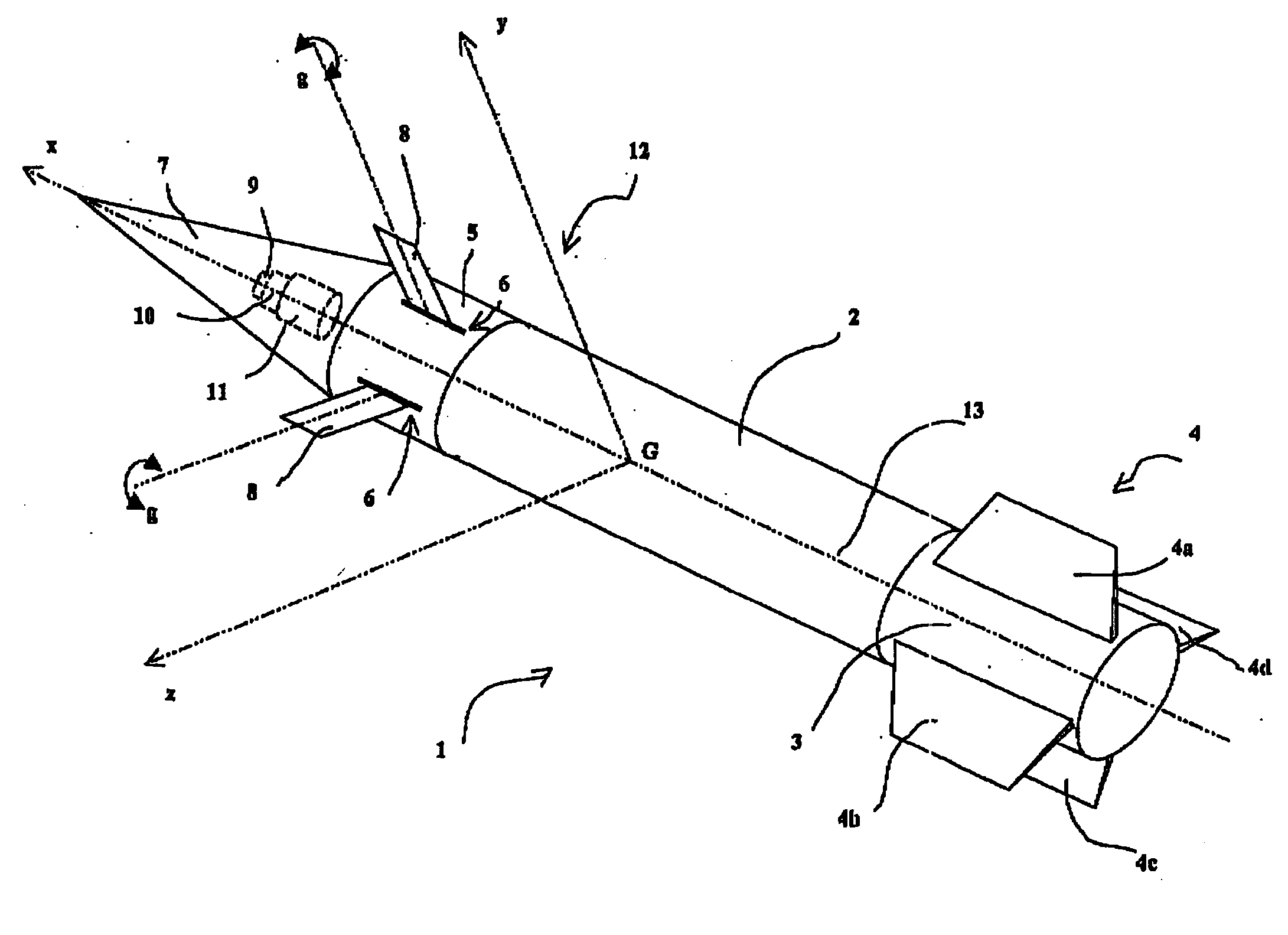
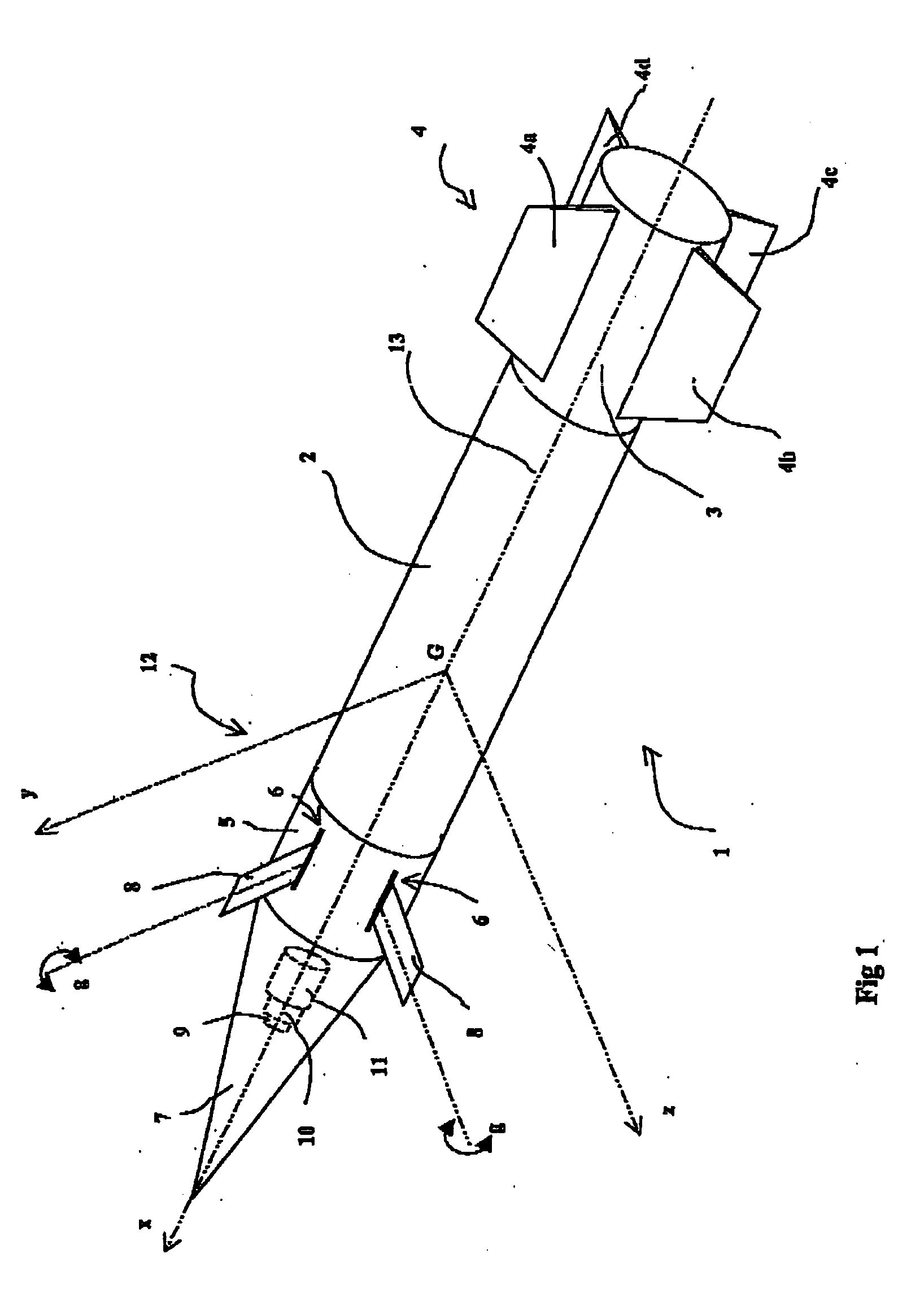
[0038]FIG. 1 shows a gliding artillery projectile 1 that incorporates a body 2 inside which a useful charge is housed (not shown), for example an explosive load or sub-munitions.

[0039] The body 2 terminates with a rear portion 3 which may enclose a propellant or else pyrotechnic generator allowing the base drag to be reduced (such generators are better known under the term, base bleed).

[0040] The rear portion 3 is fitted with a cross-shaped boattail 4 formed of four fixed fins 4a, 4b, 4c, 4d. These fins will be made, for example, as sheet steel wound around the projectile body and will deploy upon exiting the gun barrel under the effect of their own elasticity (see namely patent DE4025515).

[0041] The body 2, at its front part, has a piloting device 5 that comprises four cross-shaped canard elevons 8 deployed through slots 6 made in the projectile body. Here, only two elevons can be seen. The elevons are associated in pairs, each pair of elevons representing a piloting plane (pitc...


PUM


Abstract

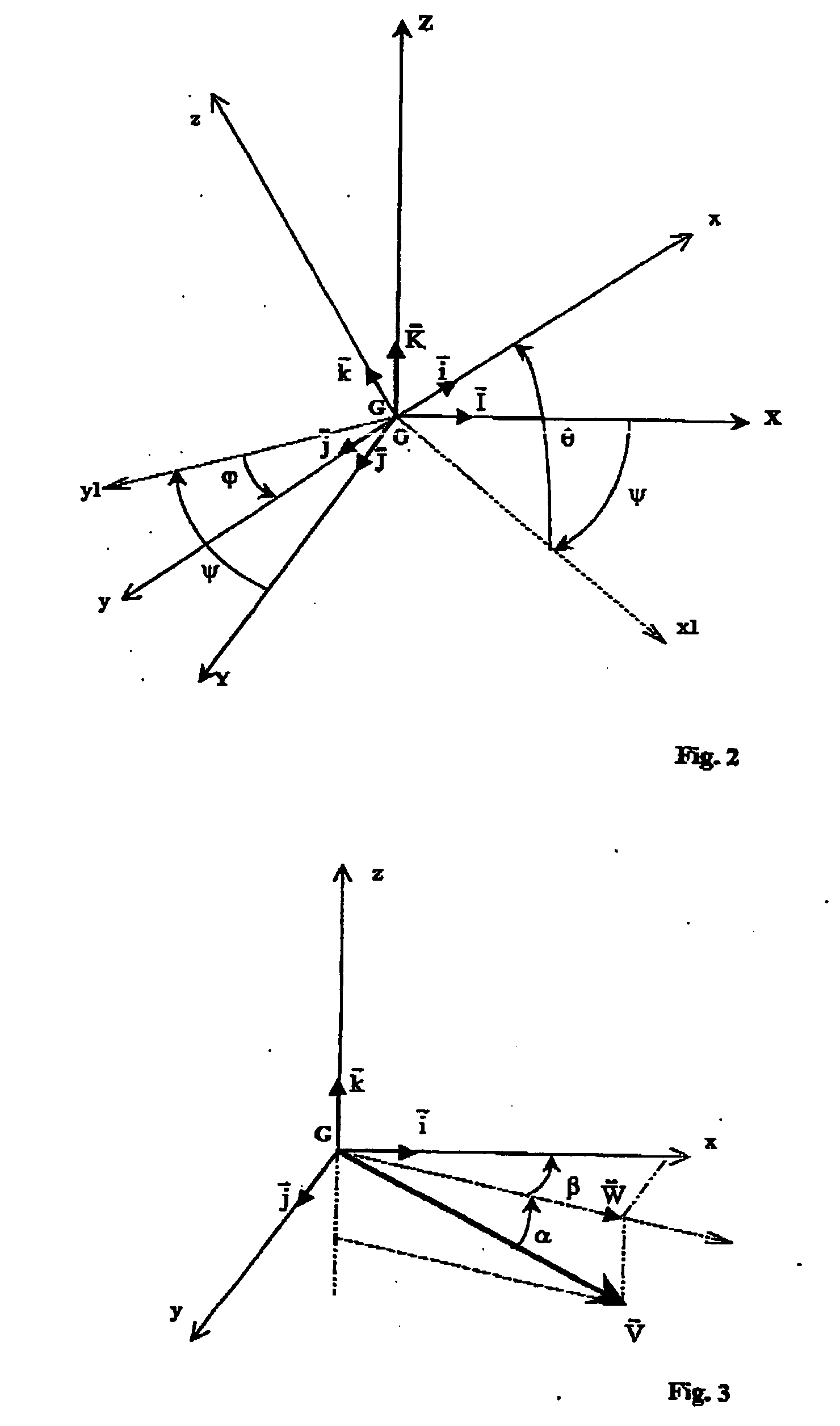
A process to control the trajectory of a spinning projectile. The projectile's accelerations are measured by means of an inertial unit in three axes within a reference linked to the projectile so as to prepare the piloting commands for the projectile's trajectory. The velocity vector V components (VX, VY, VZ) of the projectile are measured using a global positioning system (GPS) along three axes and within a land reference (GX, GY, GZ). Based on these measurements, the components (ΓXYZ) of the acceleration vector Γ are evaluated in the same land reference (GX, GY, GZ). At each of these measurements and periodical evaluations by the GPS, the Euler angles of the projectile are recalculated by combining the resultants of the velocity (V) and acceleration (Γ) measurements given by the GPS and those of the acceleration given by the inertial unit.

Description

BACKGROUND OF THE INVENTION [0001] The technical scope of the invention is that of processes enabling the control of the trajectory of a spinning projectile and namely the control of the trajectory of a projectile fired from a cannon. [0002] Projectiles fired from cannons have, in theory, a well known trajectory. However, non reproducible external factors (such as wind, temperature and atmospherical pressure) or internal factors (such as initial velocity and aerodynamic coefficients) can influence the trajectory. [0003] This results in deviations in the impact on the ground of the projectile which, at the current maximum artillery range (around 35 km) can approach, as standard deviations, 500 m in range and 150 m in direction. [0004] So as to improve firing accuracy, it is known to correct the projectile's trajectory in range by deploying one or several aerobrakes. Patent FR2786561 describes such a solution. Standard deviations in accuracy are, at 35 km, of around a hundred metres i...

Claims


Application Information

Patent Timeline
Patent Type & Authority Applications(United States)
IPC IPC(8): F41G7/00G01S19/53F41G7/36G01S5/14
CPCF41G7/346F41G7/36G01S19/53
Inventor LAMORLETTE, GERARD
Owner NEXTER MUNITIONS
Why Eureka
Try Eureka