Eureka AIR delivers breakthrough ideas for toughest innovation challenges, trusted by R&D personnel around the world.

Universal module bottom shell structure with multiple intervals and multiple installation modes

An installation method and shell structure technology, which is applied in the direction of identification devices, casings/cabinets/drawer parts, electrical equipment casings/cabinets/drawers, etc.

Inactive Publication Date: 2020-12-04
SHENZHEN MARY PHOTOELECTRICITY
View PDF9 Cites 0 Cited by
  • Summary
  • Abstract
  • Description
  • Claims
  • Application Information

AI Technical Summary

Problems solved by technology

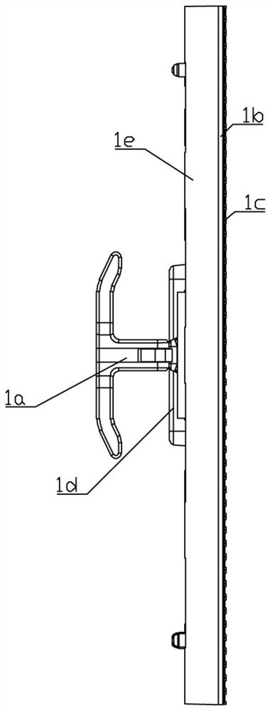
like figure 1 As shown, the LED display module structure: module mask 1c, module light board 1b, module bottom shell 1e, module handle 1a and module cover plate 1d, composed of 5 parts; LED display module installation structure To: put the module lamp board 1b on the module bottom shell 1e, align the holes, then put the module mask 1c on the top of the module lamp board 1b, and screw the module lamp board 1b to the module mask 1c Fix it on the module bottom case 1e, and then fix the module handle 1c and the module cover plate 1d on the module bottom case 1e by screws; the existing common module bottom case can only be used with one spacing, one The installation method cannot meet the needs, so in order to save costs and facilitate operations, it is now necessary to design a modular bottom shell structure with multiple spacings and multiple installation methods.

Method used


Image

  • Universal module bottom shell structure with multiple intervals and multiple installation modes
  • Universal module bottom shell structure with multiple intervals and multiple installation modes
  • Universal module bottom shell structure with multiple intervals and multiple installation modes

Examples


Embodiment Construction

[0030] In order to enable those skilled in the art to better understand the present invention, the technical solution of the present invention will be further described below in conjunction with the accompanying drawings and embodiments.

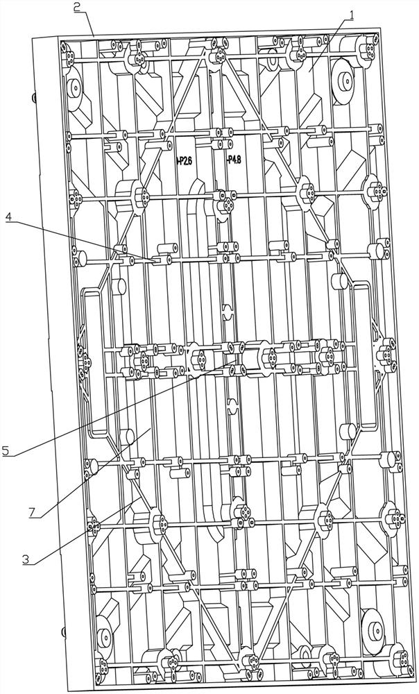
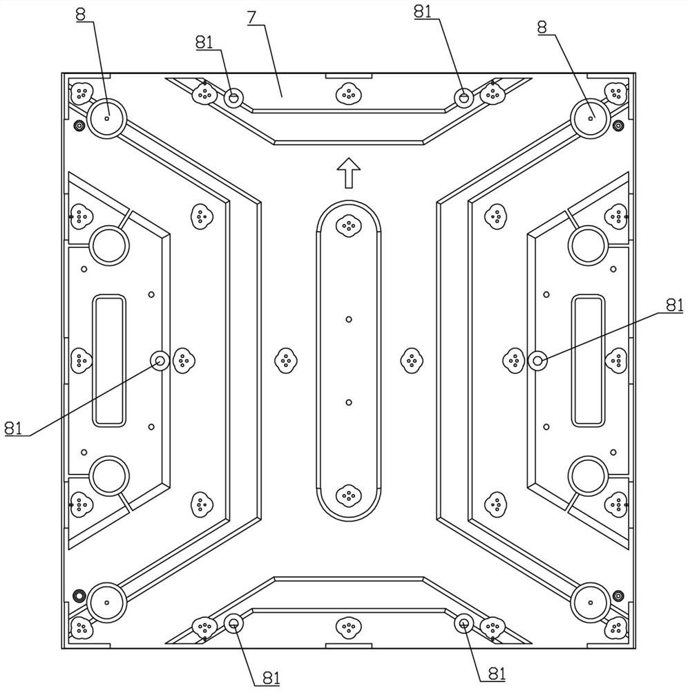
[0031] like Figure 2 to Figure 8 As shown, a modular bottom shell structure of the present invention with multiple spacings and multiple installation methods includes a bottom shell body 1 and a square frame 2, the bottom shell body 1 is provided with a square structure support frame 3, and the support frame 3 The four corners of the support frame 3 are provided with two symmetrical first mounting posts 31, the first mounting posts 31 are provided with two first mounting post holes 32, and the positions of the four corners of the support frame 3 are provided with first mounting seats 33 , the first mounting seat 33 is provided with four first mounting seat holes 34, the four sides of the support frame 3 are provided with two second mounting...


PUM


Abstract

The invention belongs to the technical field of LED display screens, and particularly relates to a universal module bottom shell structure with multiple intervals and multiple installation modes. Thestructure comprises a bottom shell body and a square frame, the bottom shell body is provided with a supporting frame of a square structure, a supporting strip is connected between two corresponding third mounting bases, the bottom shell body is provided with a cross-shaped support, the bottom shell body is provided with four transverse supporting strips, the bottom shell body is provided with twosymmetrical longitudinal supporting strips, and the bottom shell body is provided with four magnet blocks and six copper columns. The multiple universal intervals of the module bottom shell are achieved by replacing lamp panels with different intervals, hole site structures with multiple intervals are reserved in the bottom shell, so that the bottom shell can be universal, and the situation thatthe bottom shell with one interval exists in the market is avoided; a plurality of installation structures are reserved on the structural design of the bottom shell, and the first installation structure is that: a module is fixed on the box body through four magnets on the bottom shell in a magnetic attraction mode; and the second installation structure is that: six copper columns on the bottom shell are utilized, and the module is fixed to the box body through screws.

Description

technical field [0001] The invention belongs to the technical field of LED display screens, and in particular relates to a module bottom shell structure with multiple pitches and multiple installation methods. Background technique [0002] The LED display module is a display device formed by splicing many display units. The current LED display module is widely used in outdoor advertising media, program performances, large conferences and other fields. like figure 1 As shown, the LED display module structure: module mask 1c, module light board 1b, module bottom shell 1e, module handle 1a and module cover plate 1d, composed of 5 parts; LED display module installation structure To: put the module lamp board 1b on the module bottom shell 1e, align the holes, then put the module mask 1c on the top of the module lamp board 1b, and screw the module lamp board 1b to the module mask 1c Fix it on the module bottom case 1e, and then fix the module handle 1c and the module cover plate...

Claims


Application Information

Patent Timeline
IPC IPC(8): G09F9/33H05K5/02
CPCG09F9/33H05K5/0217
Inventor 刘海样凌向荣石建功
Owner SHENZHEN MARY PHOTOELECTRICITY
Why Eureka
Eureka Blog
Learn More