A general-purpose push-pull micro-twisting grounding wire device
A micro-twisting, grounding wire technology, applied in the direction of connection, conductive connection, electrical component connection, etc., can solve the problems of low clamping efficiency, easy loosening of clamping, and no anti-falling off, etc., to achieve stable and firm clamping force, structure Compact and lightweight, simple and convenient operation
- Summary
- Abstract
- Description
- Claims
- Application Information
AI Technical Summary
Problems solved by technology
Method used
Image
Examples
Embodiment 1
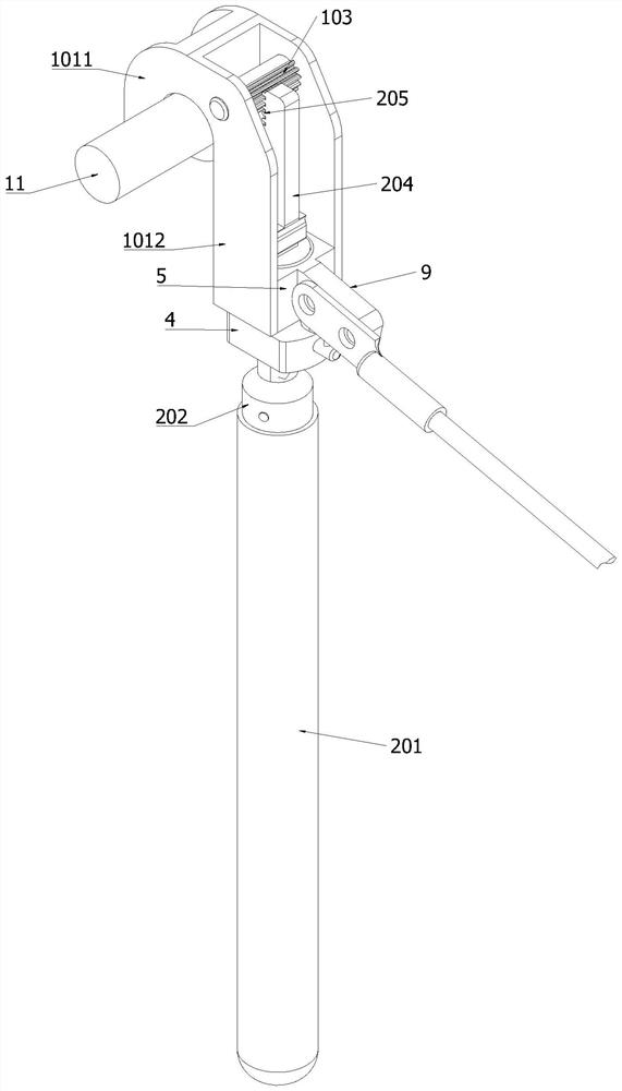
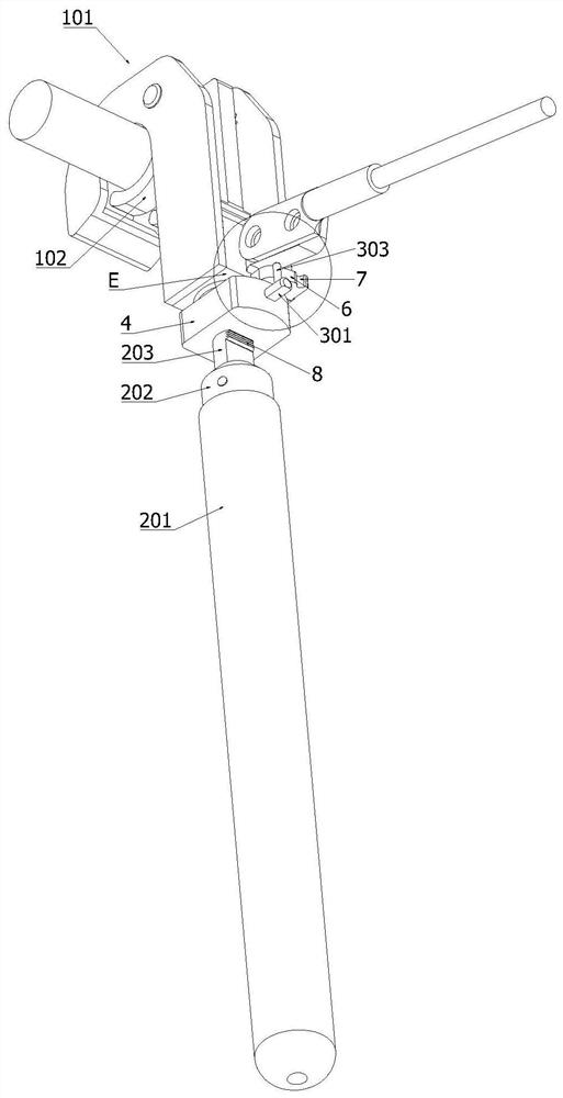
[0042] see Figure 2 to Figure 6 As shown, the present embodiment provides a general-purpose push-pull slightly twisted ground wire device, including:
[0043] The clamping part 1 includes a fixed claw 101 and a movable claw 102 that can be opened and closed relative to the fixed claw 101;
[0044] The toggle piece 2 is movably connected with the clamping part 1, and the toggle piece 2 can reciprocate and slide along the direction of its own axis to toggle the movable claw 102 to rotate relative to the fixed claw 101 to realize the clamping part 1 Zhang He;
[0045] Specifically: the fixed claw 101 includes a hook portion 1011 and two parallel ribs 1012 integrally formed with the hook portion 1011, the movable claw 102 is pivotally connected between the two parallel ribs 1012, and the movable claw 102 can be Rotate around the pivot to adjust the degree of opening and closing between it and the fixed claw 101, so as to facilitate the clamping of copper wires with different di...
Embodiment 2
[0064] This embodiment provides a general-purpose push-pull micro-twisted grounding wire device, which differs from Embodiment 1 only in that in this embodiment, the movable claw 102 and the pull rod 204 in Embodiment 1 are passed through the rack 205 and the first tooth. The meshing connection of the teeth 103 is replaced by a connecting rod connection between the movable claw 102 and the pull rod 204. Specifically, one end of the connecting rod is hinged at the end of the movable claw 102 near one end of the pivot, and the other end of the connecting rod It is hinged with the top of the pull rod 204, so that the movable claw 102 can also be pivoted by moving the insulating rod up and down.
PUM
 Abstract
Description
Claims
Application Information
 - R&D
- Intellectual Property
- Life Sciences
- Materials
- Tech Scout
- Unparalleled Data Quality
- Higher Quality Content
- 60% Fewer Hallucinations
Browse by: Latest US Patents, China's latest patents, Technical Efficacy Thesaurus, Application Domain, Technology Topic, Popular Technical Reports.
© 2025 PatSnap. All rights reserved.Legal|Privacy policy|Modern Slavery Act Transparency Statement|Sitemap|About US| Contact US: help@patsnap.com


