Disassembly tool for horizontal tails

A technology for dismantling tools and flat tails, which is applied in the direction of manufacturing tools, hand-held tools, aircraft parts, etc., can solve the problems of prolonging the production assembly cycle, increasing the assembly links of flat tails, small bearings and flat tail shafts that cannot be separated due to large clamping force, and achieving The effect of shortening the assembly work time, shortening the manufacturing cycle, and improving the efficiency of production work

Inactive Publication Date: 2016-06-08
JIANGXI HONGDU AVIATION IND GRP
View PDF5 Cites 0 Cited by
  • Summary
  • Abstract
  • Description
  • Claims
  • Application Information

AI Technical Summary

Problems solved by technology

[0003] (1) During the dismantling of the small bearing, there is a phenomenon that the small bearing and the horizontal tail shaft cannot be separated due to the large bite force. In this case, a crowbar is usually used to forcibly separate the horizontal tail from the box section at the rear of the fuselage. However, this kind of The disassembly method will cause great damage to the product, and the operation is very difficult, prolonging the production assembly cycle
[0004] (2) During the process of forcibly prying the flat tail with the crowbar, the bonding surface of the tapered bush and the large bearing will be squeezed by an unstable force. After repeated disassembly and assembly, it is easy to cause the assembly process of the tapered bush and the nut. The concentricity deviates, and the thread of the tapered bush and the nut is damaged during the installation process, which increases the scrap rate of parts and increases the manufacturing cost
Usually, the flat tail requires multiple disassembly and assembly processes. There is no effective disassembly tool for the existing disassembly and assembly process, which increases the work of the flat tail assembly link.

Method used


Image

  • Disassembly tool for horizontal tails
  • Disassembly tool for horizontal tails
  • Disassembly tool for horizontal tails

Examples


Embodiment Construction

[0019] In order to further reflect the technical means, creative features, and realized functions of the present invention, the present invention will be described in detail below with reference to specific drawings and embodiments.

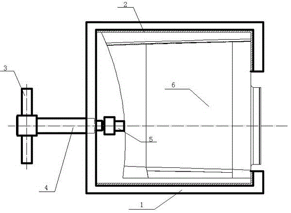
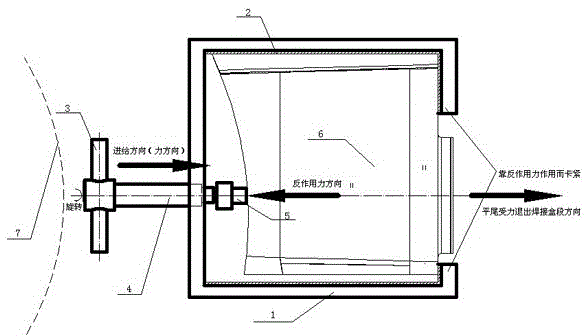
[0020] Such as figure 1 with figure 2 As shown, the flat-tail removal tool includes a positioner 1, rubber profile 2, handle 3, screw 4, pin 5. The rubber profile 2 is located at the contact surface of the positioner 1 and the rear bar section 6 of the product. The positioner 1 has bolt holes and The screw 4 is assembled, and the end surface of the screw 4 is matched with the end surface of the pin 5.

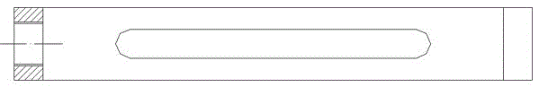
[0021] The positioner 1 is an unclosed structure with a steel groove, and its shape is based on the shape of the box section at the rear of the fuselage; and the upper and lower parts of the positioner are respectively provided with strip-shaped oval weight-reducing holes, and the left side of the positioner is provided The disassembly tool connects t...


PUM


Abstract

The invention provides a disassembly tool for horizontal tails. The disassembly tool comprises a locator, rubber sectional material, a handle, a screw and a dowel and is characterized in that the locator is a steel groove of a non-closed structure, and the appearance structure of a barrel section in the back of a fuselage is used as a reference for the appearance of the locator; a bolt hole connected to disassembly and assembly tools is formed in the left side surface of the locator; the rubber sectional material is located on the surface, making contact with the barrel section in the back of a product, of the locator, the screw is installed in the bolt hole, and the end face of the screw is matched with the end face of the dowel. According to the disassembly tool, damage to the product in the disassembly process is avoided, the efficiency of the disassembly work of the horizontal tails is greatly improved, and the disassembly time of each horizontal tail can be shortened to 10-20 minutes from 2-3 hours in the past in the repeated disassembly processes of the horizontal tails.

Description

Technical field [0001] The invention relates to the technical field of aircraft assembly, in particular to a special disassembly tool for flying flat tails. Background technique [0002] In the assembly process of the aircraft's flat tail components, because the flat tail is a cantilever beam structure, it is connected to the fuselage through a flat tail shaft (including hammer bushes, small bearings, etc.). The structural fit of the flat tail and the fuselage is an excessive fit. The current removal process of the flat tail is as follows: first use a wrench to tighten the nut connected to the hammer-shaped bushing, and move the cone-shaped bushing and the rear bar section through the relative movement of the nut and the hammer-shaped bushing. Disengage; and then use the retaining ring to disengage the small bearing from the rear bar box section, so that the flat tail part and the rear bar box section of the fuselage are completely separated. However, this flat tail disassembly ...

Claims


Application Information

Patent Timeline
Patent Type & Authority Applications(China)
IPC IPC(8): B25B27/00B64F5/00
CPCB25B27/00B64F5/00
Inventor 李汉威温金卫邹琪江帮平曾涛刘鹤齐东栋
Owner JIANGXI HONGDU AVIATION IND GRP
Why Eureka
Try Eureka