Locking structure for improving vibration resistance of steel ball locking type separation connector and connector

A technology for separating connectors and locking structures, which is applied to parts of connecting devices, devices for preventing wrong connections, flexible/rotatable wire connectors, etc., can solve the problems of high contact stress of locking structures and reduce stress , Increase the positioning function of the mandrel to achieve the effect of repeated use

Active Publication Date: 2020-12-04
CHINA AVIATION OPTICAL-ELECTRICAL TECH CO LTD
View PDF9 Cites 3 Cited by
  • Summary
  • Abstract
  • Description
  • Claims
  • Application Information

AI Technical Summary

Problems solved by technology

[0004] In order to solve the problem of excessive contact stress of the locking structure, the present invention provides a new type of locking structure that improves the vibration resistance of the steel ball locking type separation connector, which changes the contact between the steel ball and the mandrel Perfect for surface contact, reduce the stress in the contact area by increasing the contact area, and realize the repeated use of the locking structure by increasing the mandrel positioning function

Method used


Image

  • Locking structure for improving vibration resistance of steel ball locking type separation connector and connector
  • Locking structure for improving vibration resistance of steel ball locking type separation connector and connector
  • Locking structure for improving vibration resistance of steel ball locking type separation connector and connector

Examples


Embodiment Construction

[0051] In order to further explain the technical means and effects of the present invention to achieve the intended purpose of the invention, the following combined with the accompanying drawings and preferred embodiments, the locking method for improving the vibration resistance of the steel ball locking type separation connector proposed according to the present invention Structure Its concrete embodiment, structure, characteristic and effect thereof, are as follows in detail.

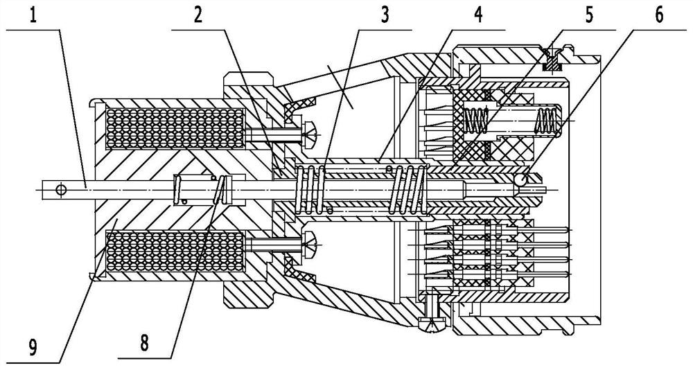
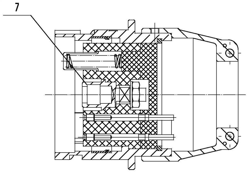
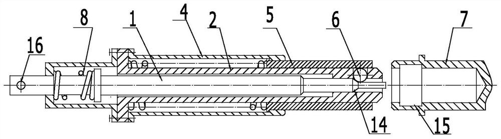
[0052] see Figure 7-13, is a structural schematic diagram of various parts of the locking structure for improving the vibration resistance of the steel ball locking type separation connector in the present invention. The locking structure includes a first locking end and a second locking end, wherein the first locking end includes The mandrel sleeve 2 and the mandrel 1 which is penetrated in the mandrel sleeve 2 and can move axially relative to the mandrel sleeve, there is also a device between the ...


PUM


Abstract

The invention relates to a locking structure for improving the vibration resistance of a steel ball locking type separation connector and the connector. The locking structure comprises a first lockingend and a second locking end, wherein the first locking end comprises a mandrel sleeve, a mandrel and a fixed lantern ring, and a spring is arranged between the front end of the mandrel and the fixedlantern ring; the front end of a spring pressing cylinder assembled outside the mandrel sleeve in a sliding mode is located between the mandrel sleeve and the fixing lantern ring, and a reset springenabling the spring pressing cylinder to move towards the stopping position is arranged between the mandrel sleeve and the spring pressing cylinder. The upper arc surface of the locking ball assembledin the through hole in the mandrel sleeve is stopped and limited by the inner circumferential surface of the spring pressing cylinder positioned on the stop position, and the lower arc surface of thelocking ball is stopped and limited by the conical reducing surface; when the first locking end and the second locking end are locked in an inserted mode, the spring pressing cylinder leaves the stopposition, the locking ball enters the inner ring groove of the second locking end along with the spring pressing cylinder, crosses the conical reducing face and enters the arc groove in the peripheryof the mandrel, and the upper arc face is limited by the inner ring groove. And the mandrel and the mandrel sleeve are circumferentially stopped from rotating.

Description

technical field [0001] The invention belongs to the field of connectors, and in particular relates to a locking structure and a connector for improving the anti-vibration capability of a steel ball locking type separation connector. Background technique [0002] Figure 1-6 It is a schematic diagram of the structure of the existing central rod type separation (falling off) connector. Three steel balls are evenly distributed on the upper circumference of the mandrel sleeve 2 of the connector. The upper spherical surface of the steel ball is limited by the spring pressure cylinder, and the lower steel ball The spherical surface is supported by the tapered surface of the mandrel, so that the position of the steel ball is completely limited. When plugged in, the spring pressure cylinder and the locking ring move to the left together after contact, when the steel ball enters the inner ring groove of the locking ring, under the force of the spring 8, the steel ball is squeezed out...

Claims


Application Information

Patent Timeline
IPC IPC(8): H01R13/639H01R24/00H01R13/641H01R35/00
CPCH01R13/639H01R35/00H01R13/641H01R24/00
Inventor 陈继利黄超
Owner CHINA AVIATION OPTICAL-ELECTRICAL TECH CO LTD
Why Eureka
Try Eureka