Plasma gun with pressing discharge switch, and using method
A technology of discharge switch and plasma gun, applied in the field of ion gun, can solve the problems of inability to adjust the angle, easy to burn the electrode, detachment, etc., and achieve the effects of convenient operation, guaranteeing normal use and simple structure
- Summary
- Abstract
- Description
- Claims
- Application Information
AI Technical Summary
Problems solved by technology
Method used
Image

Examples
Embodiment 1
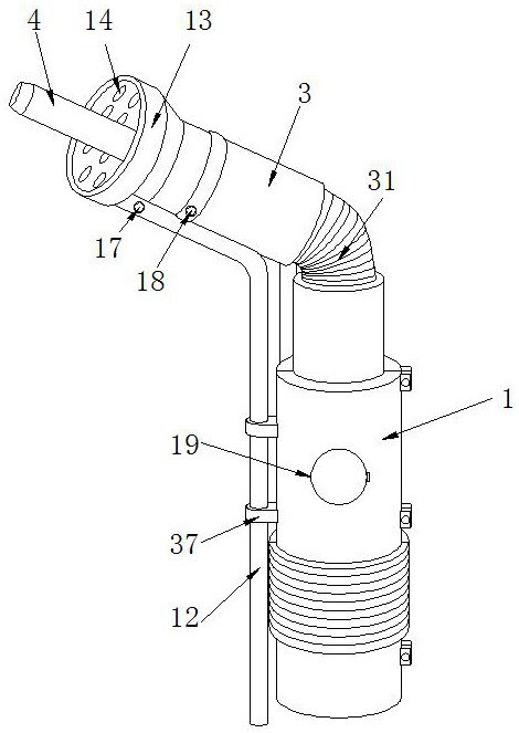
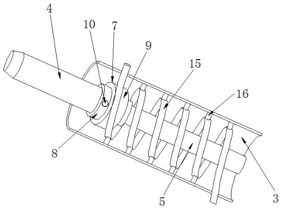
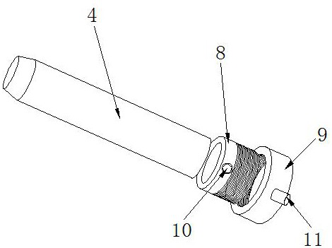
[0049] see Figure 1-9 , the present invention provides a plasma gun with a press discharge switch, including a gun body 1, a fixed barrel 2 is installed on the top of the gun body 1 through a fixing piece 2, and a protective sleeve is provided on the top of the gun body 1 and the right end of the fixed barrel 2 31, the top of the protective sleeve 31 is fixedly connected with the right end of the fixed cylinder 2, the bottom end of the protective sleeve 31 is fixed with a limit ring 32, the top of the gun body 1 is equipped with a rubber sleeve 33, and the outer surface of the rubber sleeve 33 is provided with a card slot 34 , the outer surface of the limit ring 32 fits the inner wall of the card slot 34, see figure 1 , Figure 4 and Figure 8 ; By installing the protective cover 31, the protective cover 31 can be used to protect the fixed part 2, and it is isolated from the outside world, and the protective effect is good. 31 supports, is convenient to move protective cov...
Embodiment 2
[0063] see Figure 1-11 , the present invention provides a plasma gun with a push discharge switch, including a gun body 1, the top of the gun body 1 is installed with a fixing cylinder 2 through a fixing part 2, and the fixing part 2 includes a U-shaped mounting seat 35, a mounting plate 36 and bolts Two 39, U-shaped mounting seat 35 and mounting plate 36 are respectively installed on the top of gun body 1 and the right end of fixed tube 2, bolt two 39 threads are installed on the front of U-shaped mounting seat 35, and the front of mounting plate 36 offers threaded holes 38. The tail end of the bolt two 39 passes through the U-shaped mounting seat 35 and is threaded on the inner wall of the threaded hole 38. Figure 10 and Figure 11 ; By installing the U-shaped mounting base 35 and the mounting plate 36 and the bolt 2 39 as the fixture 2, the angle of the stationary cylinder 2 can be adjusted as required, thereby realizing the adjustment of the working angle of the plasma ...
PUM
 Abstract
Description
Claims
Application Information
 - R&D Engineer
- R&D Manager
- IP Professional
- Industry Leading Data Capabilities
- Powerful AI technology
- Patent DNA Extraction
Browse by: Latest US Patents, China's latest patents, Technical Efficacy Thesaurus, Application Domain, Technology Topic.
© 2024 PatSnap. All rights reserved.Legal|Privacy policy|Modern Slavery Act Transparency Statement|Sitemap