Supercharge Your Innovation With Domain-Expert AI Agents!

Anti-fog automatic instrument

An instrument and anti-fog technology, which is applied in chemical instruments and methods, electrical components, chassis/cabinet/drawer parts, etc. Effect

Inactive Publication Date: 2020-12-04
西安安迈工业自动化技术有限公司
View PDF1 Cites 1 Cited by
  • Summary
  • Abstract
  • Description
  • Claims
  • Application Information

AI Technical Summary

Problems solved by technology

[0005] The purpose of the present invention is to solve the problem that the prior art motorcycle instrument is not easy to clear and affects the normal use of the driver, and proposes an anti-fog automatic instrument

Method used


Image

  • Anti-fog automatic instrument
  • Anti-fog automatic instrument

Examples


Embodiment 1

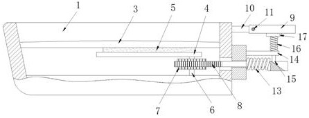
[0022] Example 1 as figure 1 As shown, this anti-fog automatic instrument includes a housing 1 and an instrument panel 2. The instrument panel 2 is arranged inside the housing 1. A protective shell 3 is arranged inside the housing 1 and above the instrument panel 2. The instrument panel The middle part of 2 and below the protective case 3 are provided with two rotating rods 4, the lower ends of the two rotating rods 4 are connected to the instrument panel 2 through the first rotating shaft 6, and the upper surfaces of the two rotating rods 4 are provided with wipers. Bar 5, the upper surfaces of the two scraping bars 5 are all offset against the lower surface of the protective case 3, the rod walls of the two first rotating shafts 6 are fixedly sleeved with gears 7, and a double-sided rack is arranged between the two gears 7 8. The double-sided rack 8 is meshed with the two gears 7. The lower end of the double-sided rack 8 extends to the outside of the housing 1. The rear end ...

Embodiment 2

[0023] Embodiment 2 is on the basis of embodiment 1 such as figure 2 As shown, its pushing mechanism includes a pressure plate 9 and a push rod 15, and the lower end of the housing 1 is provided with two fixed blocks 10 and a limit rod 14 in turn from top to bottom, and the pressure plate 9 is arranged between the two fixed blocks 10 and Both ends are rotatably connected with the corresponding fixed block 10 through the second rotating shaft 11. The push rod 15 is slidably arranged inside the limit rod 14 and the lower end is inclined. The inclined surface of the push rod 15 matches the slope groove, and the push rod 15 The upper end of the push rod 15 is fixedly provided with a pressure block 17, and the upper end rod wall of the push rod 15 is movably sleeved with a second spring 16, and the two ends of the second spring 16 are fixedly connected to the corresponding pressure block 17 and the limit rod 14 respectively.

Embodiment 3

[0024] Embodiment 3 is such as on the basis of embodiment 1 figure 1 As shown, torsion springs 12 are movably sleeved on both sides of its second rotating shaft 11, and the two ends of the torsion springs 12 on both sides are respectively fixedly connected to the corresponding fixed blocks 10 and the second rotating shaft 11. In the natural state, the torsion springs The elastic force of 12 can make pressing plate 9 be horizontal state


PUM


Abstract

The invention relates to the technical field of automatic instruments, and discloses an anti-fog automatic instrument. The anti-fog automatic instrument comprises a shell body and an instrument panel,wherein the instrument panel is arranged in the shell body, a protective shell is arranged in the shell body and located above the instrument panel, two rotating rods are arranged in the middle of the instrument panel and located below the protective shell, the lower ends of the two rotating rods are rotationally connected with the instrument panel through first rotating shafts, scraping strips are arranged on the upper surfaces of the two rotating rods, the upper surfaces of the two scraping strips abut against the lower surface of the protective shell, the rod walls of the two first rotating shafts are fixedly sleeved with gears, a double-sided rack is arranged between the two gears, the double-sided rack is connected with the two gears in a meshed mode, the lower end of the double-sided rack extends out of the shell body, and the rear end of the double-sided rack is movably connected with a first spring in a sleeved mode. According to the anti-fog automatic instrument, fog on the instrument can be scraped conveniently.

Description

technical field [0001] The invention relates to the technical field of automatic instruments, in particular to an anti-fog automatic instrument. Background technique [0002] As the most important driving reference for motorcycle drivers, the meter is mainly to control the driving situation of the car through the display of various data and indicator lights on the dial to ensure driving safety. However, the existing motorcycle meter has a large temperature difference between inside and outside. Under the circumstances, the inner layer of the transparent observation cover on the instrument shell is prone to generate a layer of fog, which affects the visualization effect of the instrument and causes the driver to read the indicator pointer. [0003] Among them, the patent No. CN210062681U discloses an anti-fog automatic instrument. When in use, an air extraction device and a cooling device are respectively arranged at both ends of the protective cover, and a guide channel is p...

Claims


Application Information

Patent Timeline
Patent Type & Authority Applications(China)
IPC IPC(8): H05K5/02B08B1/00
CPCH05K5/0217B08B1/165
Inventor 祖侥侥
Owner 西安安迈工业自动化技术有限公司
Features
  • R&D
  • Intellectual Property
  • Life Sciences
  • Materials
  • Tech Scout
  • Unparalleled Data Quality
  • Higher Quality Content
  • 60% Fewer Hallucinations
Learn More