Apparatus and method for determining position of at least one object

A technology of equipment and objects, applied in the direction of measuring devices, using re-radiation, re-radiation of electromagnetic waves, etc., to achieve the effects of stable system performance, improved signal-to-noise ratio, and large equipment effective distance

Pending Publication Date: 2020-12-04
ROBERT BOSCH GMBH
View PDF2 Cites 1 Cited by
  • Summary
  • Abstract
  • Description
  • Claims
  • Application Information

AI Technical Summary

Problems solved by technology

However, this is not a system requirement for lidar, but b

Method used


Image

  • Apparatus and method for determining position of at least one object
  • Apparatus and method for determining position of at least one object
  • Apparatus and method for determining position of at least one object

Examples


Embodiment Construction

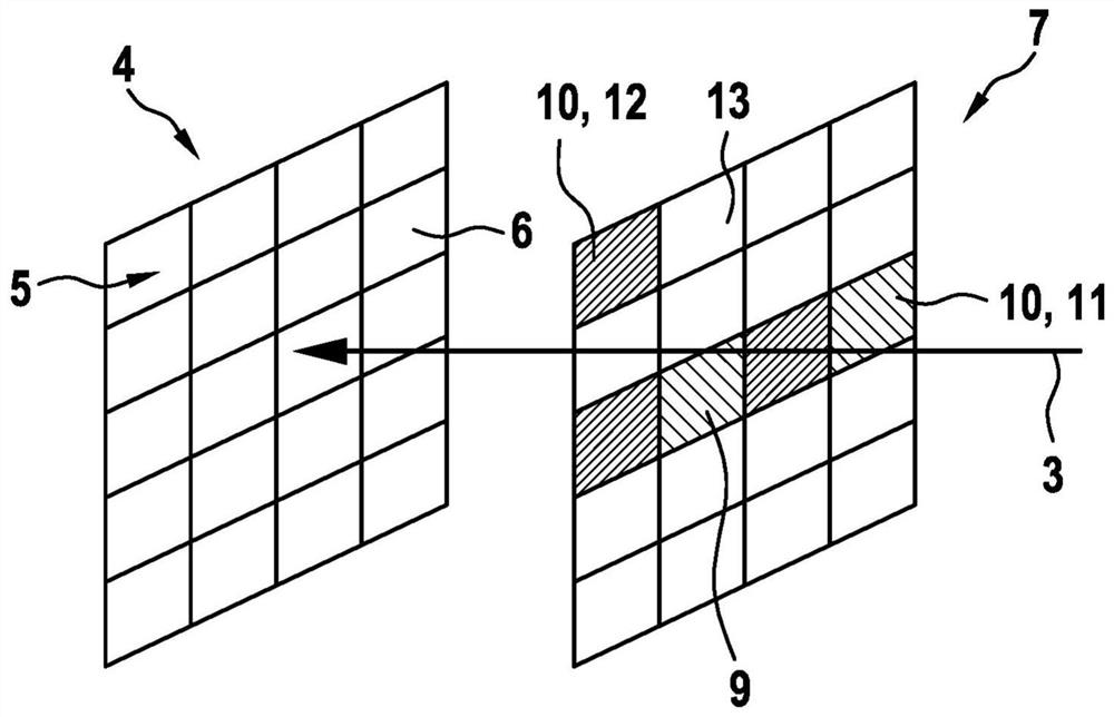
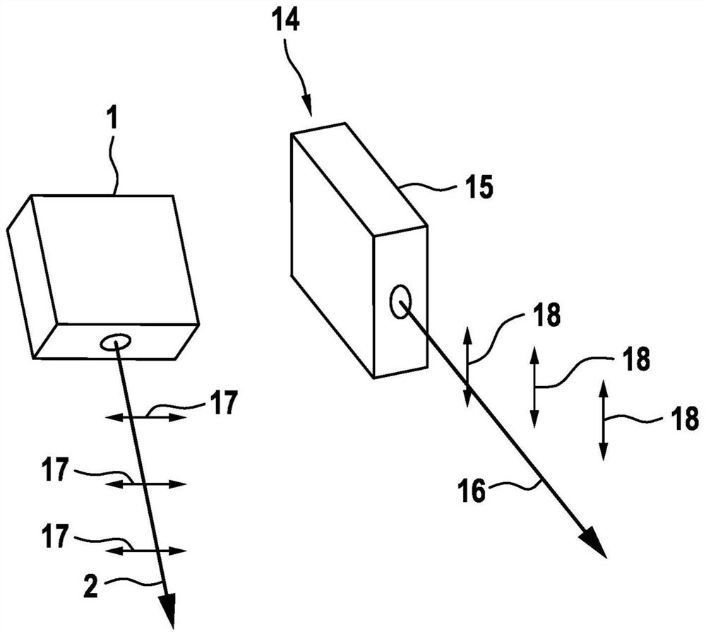
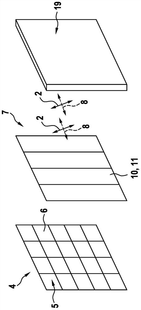
[0041] The device according to the invention has a first emitter 1 which is provided for emitting a first emission light signal 2 . This transmitted light signal 2 is reflected on the object whose position is to be determined and propagates back to the device as a received light signal 3 . In this case, the received light signal strikes a detector 4 with a pixel matrix 5 having at least one pixel 6 .

[0042] exist figure 1 shows a device with a passive polarization adaptation unit 7 arranged to control the polarization of the received optical signal 3 as a function of the ambient optical signal 8 . In this case, the passive polarization adaptation unit 7 has a polarization filter matrix 9 . The polarizing filter matrix 9 has a plurality of static polarizing filters 10 . In the exemplary embodiment shown here, polarization filters 11 for vertical polarization and polarization filters 12 for parallel polarization alternate in a “checkerboard pattern”. Passing spaces 13 are ...


PUM


Abstract

An apparatus for determining a position of at least one object is proposed, the apparatus comprising at least one first emitter (1) that is configured to emit a first transmission light signal (2) which propagates from the apparatus to the object, and the apparatus comprising at least one detector (4) that is configured to detect a reception light signal (3) which propagates from the object to thedetector (4), the detector (4) comprising at least one pixel matrix (5) with at least one pixel (6), the apparatus also comprising at least one passive polarization adaptation unit (7) that is configured to control a polarization of the reception light signal (3) depending on an ambient light signal (8). Further, a method is proposed for determining a position of at least one object by means of such an apparatus, in which method a measurement-control element measures a first signal-to-noise ratio at a first measurement time; and the measurement-control element measures a second signal-to-noise ratio at a second measurement time; and the measurement-control element controls the second emitter to emit the second transmission light signal in place of the first one should the second signal-to-noise ratio be less than the first signal-to-noise ratio.

Description

technical field [0001] The invention relates to a device for determining the position of at least one object, wherein the device has at least one first transmitter which is arranged to emit a first transmitted light signal, the first transmitted light signal Propagates from the device to the object, wherein the device has at least one detector arranged to detect a received light signal propagating from the object to the detector, wherein the detector has at least one At least one pixel matrix for one pixel. [0002] The invention also relates to a method for determining the position of at least one object by means of such a device. Background technique [0003] This device is also known as lidar (originally Portmonteau, a combination of light and radar). Lidar can be used, among other things, to determine the position of an object relative to itself and relative to other objects. Possible areas of application arise, for example, in the automotive sector. The functional p...

Claims


Application Information

Patent Timeline
IPC IPC(8): G01S17/42G01S17/931G01S7/481G01S7/487G01S7/499
CPCG01S7/4814G01S7/4816G01S7/487G01S7/499G01S17/42G01S17/931G01S7/4815G01S17/06
Inventor N·埃尔曼N·霍伊斯纳M·卡米尔S·施皮斯贝格尔
Owner ROBERT BOSCH GMBH
Why Eureka
Try Eureka