Easy-to-demold injection mold with buffering effect

An injection mold and buffering technology, applied in the field of easy-release injection molds, can solve problems such as damage to injection products, and achieve the effect of avoiding damage and facilitating separation.

Inactive Publication Date: 2020-12-08
黄家军
View PDF4 Cites 4 Cited by
  • Summary
  • Abstract
  • Description
  • Claims
  • Application Information

AI Technical Summary

Problems solved by technology

[0005] The purpose of the present invention is to solve the problem that most traditional injection molds easily cause damage to injection molded products during the demoulding process, and to provide an easy-to-release injection mold that can effectively protect injection molded products and has a buffering effect

Method used


Image

  • Easy-to-demold injection mold with buffering effect
  • Easy-to-demold injection mold with buffering effect
  • Easy-to-demold injection mold with buffering effect

Examples


Embodiment 1

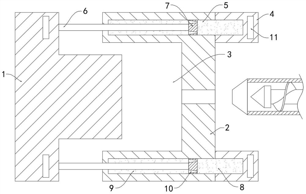
[0022] Such as Figure 1-2 As shown, a kind of easy-release injection mold with cushioning effect includes a movable mold 1 and a fixed mold 2, an injection cavity 3 is formed between the movable mold 1 and the fixed mold 2, and the plastic solution is injected into the injection cavity through the injection hole during injection molding 3, the above is the prior art, and will not be repeated here.

[0023] The upper and lower ends of the outer wall of the fixed mold 2 are fixedly connected with a fixed block 4, and the fixed mold 2 is provided with a buffer cavity 5 corresponding to the fixed block 4. The buffer cavity 5 extends to the fixed block 4 and is set. Filled with electrorheological fluid, the viscosity of the electrorheological fluid will change with the strength of the electric field it is in. When the electric field strength becomes larger, the viscosity increases, and when the electric field strength becomes smaller, the viscosity decreases.

[0024] The upper a...

Embodiment 2

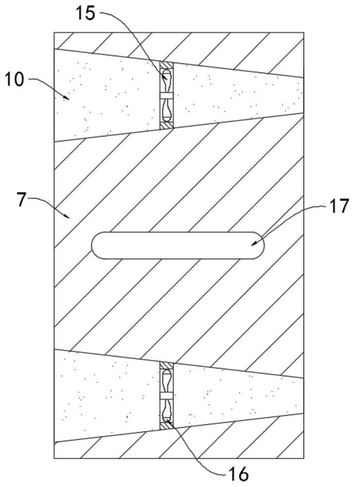
[0035] Such as image 3 As shown, the difference between this embodiment and Embodiment 1 is that each communication hole 10 is fixedly connected with a rotating fan 15 perpendicular to the axis of the communication hole 10, and the end of each blade of the rotating fan 15 is fixed. A magnetic block 16 is connected, and a magnetic plate 17 is fixedly embedded in the sliding block 7 .

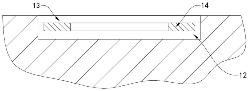
[0036]In this embodiment, after the injection molded product is solidified, while the movable mold 1 is moving away from the fixed mold 3, the electrorheological fluid in the buffer cavity 5 will flow, driving the rotating fan 15 to rotate, and the rotating fan 15 on the blades The magnetic block 16 cuts the magnetic induction line of the magnetic plate 17 to generate a current, so that the electrode plate 11, the piezoelectric plate 14 and the vibrating plate 13 conduct current, and no additional power supply is needed, which saves energy.


PUM


Abstract

The invention belongs to the field of injection molding, and particularly relates to an easy-to-demold injection mold with a buffering effect. The easy-to-demold injection mold comprises a movable mold body and a fixed mold body. An injection molding cavity is formed between the movable mold body and the fixed mold body, fixed blocks are fixedly connected to the upper end and the lower end of theouter side wall of the fixed mold body, and buffering cavities in one-to-one correspondence with the fixed blocks are arranged in the fixed mold body and extend into the fixed blocks. Electrorheological fluid is contained in the buffer cavities, horizontally-arranged positioning rods are fixedly connected to the upper end and the lower end of the inner side wall of the movable mold body, the ends,away from the movable mold body, of the positioning rods extend into the buffering cavities and are fixedly connected with sliding blocks, and the sliding blocks are in sealed sliding connection withthe inner side walls of the buffering cavities. By arranging a demolding mechanism, after an injection molding product is immobilized, an electrified piezoelectric plate can drive a vibrating plate to vibrate, that is, the side wall of the injection molding cavity can vibrate, and the injection molding product can be separated from the injection mold conveniently. The number of vibrating points in the injection molding cavity is large, the injection molding product can be integrally disengaged from the injection molding cavity, and damage to the injection mold can be effectively avoided.

Description

technical field [0001] The invention belongs to the field of injection molding, and in particular relates to an easy-release injection mold with buffer function. Background technique [0002] In the injection molding process, the driving mechanism such as the push rod motor will drive the movable mold to reciprocate in the horizontal direction. When the movable mold and the fixed mold are combined together, they will be injected through the injection hole. When the plastic solution in the injection hole is cooled and solidified, Then the movable mold is separated from the fixed mold for demoulding. [0003] Injection molds are generally composed of a moving mold and a fixed mold. Before injection molding, the moving mold must be combined with the fixed mold. In most traditional injection molds, the driving motor will directly drive the moving mold to move in the direction of the fixed mold, while the fixed mold and the fixed mold There is a hard contact between the movable ...

Claims


Application Information

Patent Timeline
Patent Type & Authority Applications(China)
IPC IPC(8): B29C45/26B29C45/84B29C45/40B29C45/64
CPCB29C45/2602B29C45/84B29C45/40B29C45/64B29C2045/645
Inventor 黄家军
Owner 黄家军
Why Eureka
Try Eureka