

Air conditioner
A technology for air conditioners and compressors, applied in high-efficiency regulation technology, compressors, refrigerators, etc., can solve problems such as refrigerant liquefaction retention and oil retention, and achieve the effect of preventing oil shortage and improving comfort
- Summary
- Abstract
- Description
- Claims
- Application Information
AI Technical Summary
Problems solved by technology
Method used
Image

Examples
no. 1 approach
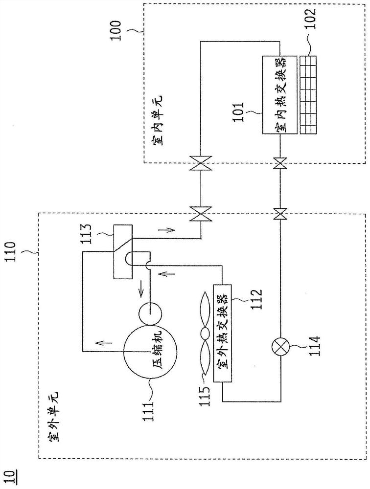
[0040] Hereinafter, the first embodiment of the present invention will be described in detail with reference to the accompanying drawings.figure 1 It is a schematic configuration diagram of the air conditioner 10 according to the first embodiment, and shows a refrigeration cycle applied to the air conditioner 10 .
[0041] The air conditioner 10 is composed of an indoor unit (indoor unit) 100 and an outdoor unit (outdoor unit) 110 . The air conditioner 10 includes an indoor heat exchanger 101 on the indoor unit 100 side, and a compressor 111 , outdoor heat exchanger 112 , four-way valve 113 , and expansion valve 114 on the outdoor unit 110 side on the path of the refrigeration cycle in the air conditioner 10 . In addition, the indoor unit 100 is equipped with an indoor fan 102 for sending the air heat-exchanged by the indoor heat exchanger 101 into the room, and the outdoor unit 110 is equipped with an outdoor fan 115 for sending the air into the room. Outdoor heat exchanger 1...
no. 2 approach 〕
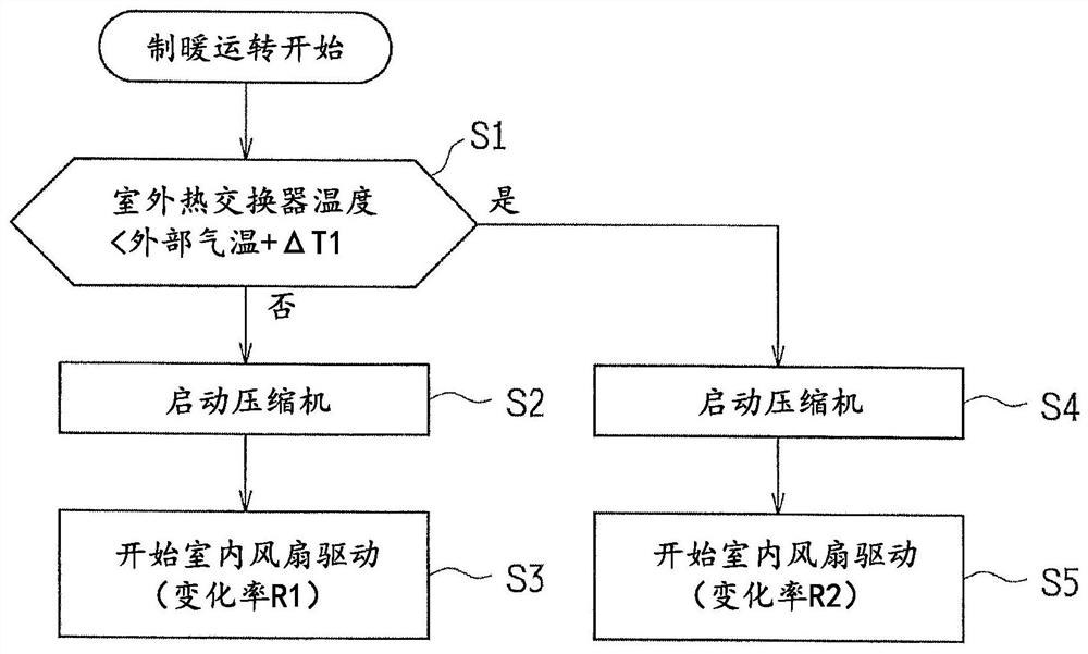
[0065] Figure 6 It is a flowchart showing start-up control at the start of operation of the air conditioner 10 according to the second embodiment. In addition, in the activation control of the second embodiment, the same steps as those of the activation control of the first embodiment are assigned the same step numbers, and detailed description thereof will be omitted.
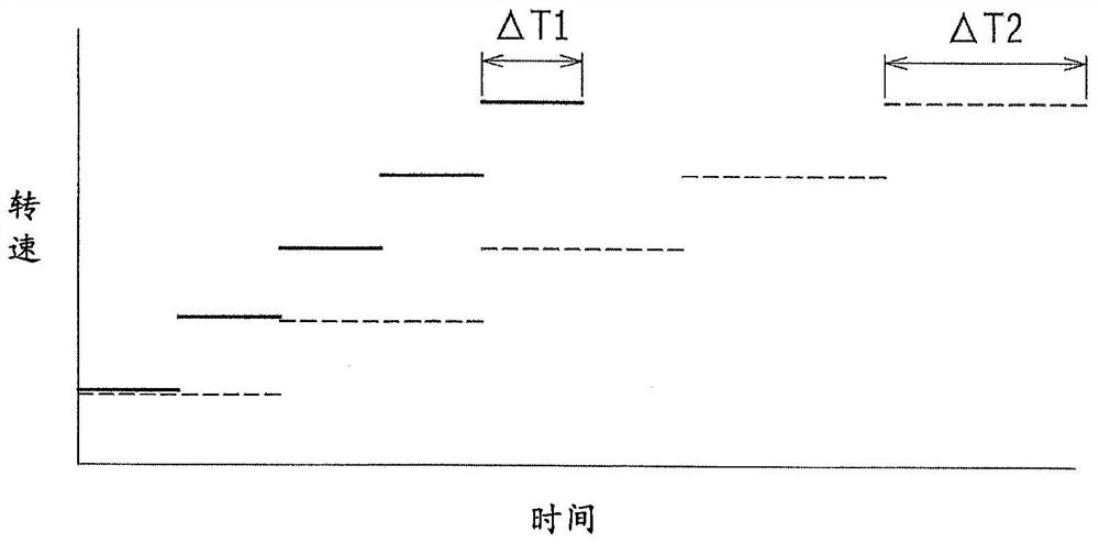
[0066] When the air conditioner 10 starts driving, in the startup control of the second embodiment, it is first determined whether or not the compressor 111 is in the sleep state (S1). The judgment here serves as figure 2 of the S1 step in the start-up control, but can also be used as Figure 4 The S1’ step in the start control can also be used with Figure 5 The startup control of the same method uses two steps of S1 and S1'. This is also the same as step S16 described later.
[0067] When the compressor 111 is not in the sleep state ("No" in S1), the activation operation of the air conditioner 10 incl...
no. 3 approach 〕
[0076] In the first and second embodiments described above, the sleep state of the compressor 111 was determined based on the outdoor heat exchanger temperature and the discharge temperature, but such determination requires a temperature sensor. In recent years, an air conditioner in which the number of temperature sensors used has been reduced as much as possible has been developed, and it is considered effective if such an air conditioner can determine a sleep state without using a temperature sensor.
[0077] Figure 8 It is a flowchart showing start-up control at the start of operation of the air conditioner 10 according to the third embodiment. In addition, in the start-up control of the third embodiment, the same step numbers as those of the start-up control of the first and second embodiments are given the same step numbers, and detailed description thereof will be omitted.
[0078] When the air conditioner 10 starts driving, in the startup control of the second embodi...
PUM
 Abstract
Description
Claims
Application Information