Industrial environment-friendly dust removal equipment convenient for dust removal

A dust removal equipment and industrial technology, applied in the field of industrial environmental protection dust removal equipment, can solve the problems of inconvenient use, physical injury, inability to clean and discharge dust, etc., and achieve the effects of increasing cleaning effect, high reliability and novel design.

Inactive Publication Date: 2020-12-11
刘亚玲
View PDF1 Cites 4 Cited by
  • Summary
  • Abstract
  • Description
  • Claims
  • Application Information

AI Technical Summary

Problems solved by technology

[0002] In the process of industrial production and processing, a lot of dust will be generated. If the dust in the air is not collected, when the workers inhale too much dust, it will cause great harm to the body.
[0003] Due to the simple structure of traditional dust removal equipment, the pipe for sucking dust can only be in one direction, which is inconvenient to use, and there will be other floating things in the air, such as leaves, dandelions and cotton, etc. Not prone to decay and needs to be collected and disposed of separately from dust
[0004] Chinese patent (notification number: CN211027451U) discloses an industrial dust removal equipment that is easy to clean dust, including a box body, a feeding structure and a filtering structure. The feeding structure includes a feeding pipe, a pipe head and a first--motor. The top of the box body is rotatably provided with a feed pipe, and the other end of the feed pipe is rotatably provided with a pipe head, which is in the shape of a trumpet and is used to improve the effect of feeding. The inside of the feed pipe is fixedly provided with The exhaust fan is used to generate suction to suck the dust in the air into the box. The filter structure includes a support frame, a second motor and a third gear. Both sides of the box are respectively provided with chutes, and the two A support frame is slidingly arranged between the above chute. Although the device can ensure the effective cleaning of dust to a certain extent, it cannot effectively clean and discharge the dust accumulated inside the device in actual operation. Therefore, it is necessary to further improvement

Method used


Image

  • Industrial environment-friendly dust removal equipment convenient for dust removal
  • Industrial environment-friendly dust removal equipment convenient for dust removal
  • Industrial environment-friendly dust removal equipment convenient for dust removal

Examples


Embodiment 1

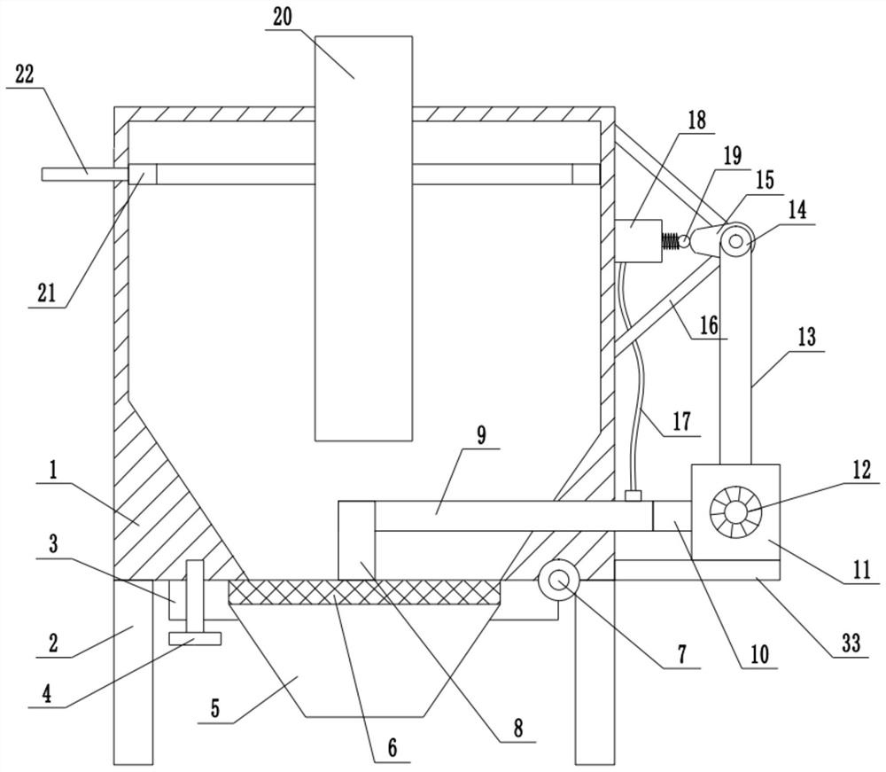
[0030] refer to Figure 1~5 , in an embodiment of the present invention, an industrial environment-friendly dedusting device for cleaning dust, including a dust removal box 1, and support legs 2 are installed on both sides of the lower end of the dust removal box 1, to ensure the support and fixation of the entire device, the dust removal box 1 An air injection ring 21 is installed on the upper end of the inner wall, and the air injection ring 21 is internally connected with an air intake pipe 22. The inner wall of the air injection ring 21 is provided with a number of obliquely arranged air injection holes 31, and the air injection holes 312 are obliquely arranged on the inner wall of the air injection ring 21, so that the air injection ring 21 The blown industrial flue gas is sprayed tangentially along the inner wall of the dust removal box 1, thereby increasing the effect of cyclone dust removal. An exhaust pipe 20 is installed vertically on the top of the dust removal box 1...

Embodiment 2

[0032] In another embodiment of the present invention, the difference between this embodiment and the above-mentioned embodiment is that the rear end of the cam 15 is rotatably connected to the limit frame 16, and the limit frame 16 is fixed on the outer wall of the dust removal box 1, and then the The limiting function of the driven pulley 14 and the cam 15 during rotation.

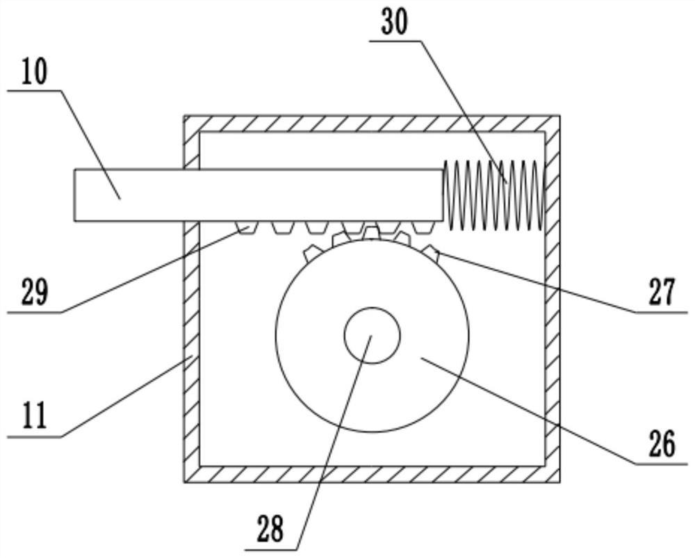
[0033]In the present invention, when working, the intake pipe 22 introduces industrial smoke, and the industrial smoke is sprayed out from the air injection hole 31. Under the setting effect of the outlet tube 20, the cyclone dust removal is realized, and the dust falls into the upper end of the filter screen 6 along the bottom end of the outlet tube 20 At the same time, the drive motor 12 is started, and the drive motor 12 drives the drive wheel 26 to rotate, so that the ring teeth 27 and the rack 29 are periodically engaged, and under the action of the moving spring 30, the swing scraper 8 is scraped al...


PUM


Abstract

The invention relates to the technical field of dust removal equipment, and discloses industrial environment-friendly dust removal equipment convenient for dust removal. The equipment comprises a dustremoval box, an air injection ring is arranged at the upper end of the inner wall of the dust removal box, an exhaust funnel is arranged at the top end of the dust removal box in the vertical direction, and a rotating shaft is arranged on the right side of the bottom end of the dust removal box, and a rotating plate is hinged to the left side of the rotating shaft; a groove is formed in the middle of the upper end of the rotating plate, a filter screen is placed in the groove, the left side of the rotating plate is detachably fixed to the bottom of the dust removal box through bolts, a supporting plate is installed at the bottom of the right side of the dust removal box, a driving box is installed at the upper end of the supporting plate, a driving shaft is installed in the driving box, and a driving wheel is installed in the middle of the driving shaft; and racks evenly arranged at the lower end of a moving rod are engaged with the upper ends of ring teeth, the left side of the moving rod penetrates through the driving box to be connected with a hollow column, and the left end of the hollow column is connected with a swing scraper. According to the industrial gas dust removal equipment, the cyclone dust removal principle is utilized, the dust removal effect on dust in industrial gas is achieved, and meanwhile air injection can be conducted while the swing scraper moves leftwards and rightwards.

Description

technical field [0001] The invention relates to the technical field of dust removal equipment, in particular to industrial environmental protection dust removal equipment which is convenient for cleaning dust. Background technique [0002] In the process of industrial production and processing, a lot of dust will be generated. If the dust in the air is not collected, when workers inhale too much dust, it will cause great harm to the body. [0003] Due to the simple structure of traditional dust removal equipment, the pipe for sucking dust can only be in one direction, which is inconvenient to use, and there will be other floating things in the air, such as leaves, dandelions and cotton, etc. Not prone to decay and needs to be collected and disposed of separately from dust. [0004] Chinese patent (notification number: CN211027451U) discloses an industrial dust removal equipment that is easy to clean dust, including a box body, a feeding structure and a filtering structure. ...

Claims


Application Information

Patent Timeline
Patent Type & Authority Applications(China)
IPC IPC(8): B01D50/00
CPCB01D50/20Y02A50/2351
Inventor 刘亚玲
Owner 刘亚玲
Why Eureka
Try Eureka