
Sawing mechanism for automatic photovoltaic panel frames with different lengths
A photovoltaic panel, automatic technology, applied in the field of mechanical processing, can solve the problems of low utilization rate, inability to fix the photovoltaic panel frame, and inability to ensure sawing stability and accuracy, etc., to improve utilization, improve efficiency, and simple operation. handy effect
- Summary
- Abstract
- Description
- Claims
- Application Information
AI Technical Summary
Problems solved by technology
Method used
Image

Examples
Embodiment Construction
[0017] Below in conjunction with the accompanying drawings, the components and their interrelationships of the present invention will be described.
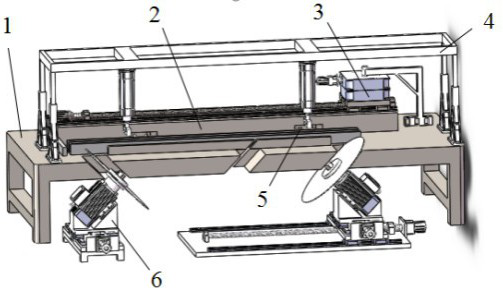
[0018] Overall structure of the present invention is as attached figure 1 As shown, the motion platform (2) is fixed on the workbench (1), the rotation mechanism (3) is connected with the sliding platform one (14) on the motion platform (2), and the fixed frame (4) is connected with the workbench (1) , the pushing alignment mechanism (5) is installed in the workbench (1), and the sawing mechanism (6) is fixed at the bottom of the workbench (1).
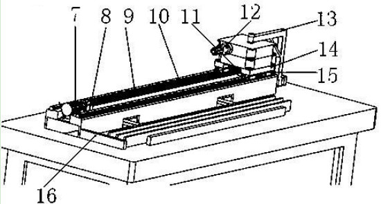
[0019] as attached figure 2 As shown, the motion platform (2) is characterized in that: the two ends of the long ball screw (10) are fixed on the screw fixing seat (9) and the screw support seat, and the slide table one (14) is fixed on the four slides On the block (15), the lead screw nut is fixed on the bottom of slide table one (14), the motor (8) is fixed on the motion platform (2...
PUM
 Abstract
Description
Claims
Application Information