[0031] The following will clearly and completely describe the technical solutions in the embodiments of the present invention with reference to the accompanying drawings in the embodiments of the present invention. Obviously, the described embodiments are only some, not all, embodiments of the present invention.
[0032] In describing the present invention, it should be understood that the terms "upper", "lower", "front", "rear", "left", "right", "top", "bottom", "inner", " The orientation or positional relationship indicated by "outside", etc. is based on the orientation or positional relationship shown in the drawings, and is only for the convenience of describing the present invention and simplifying the description, rather than indicating or implying that the referred device or element must have a specific orientation, so as to Specific orientation configurations and operations, therefore, are not to be construed as limitations on the invention.
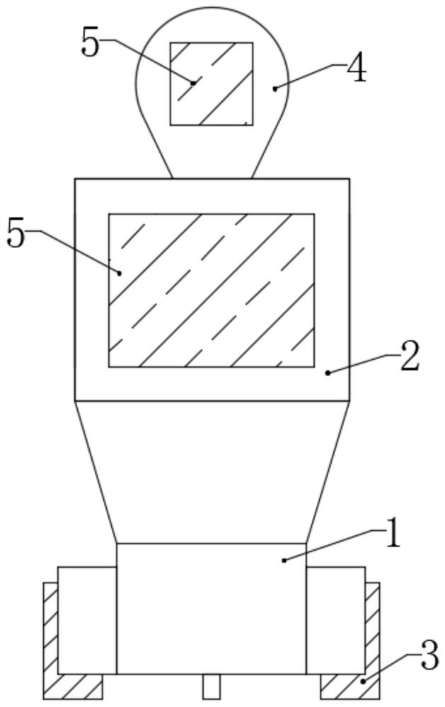
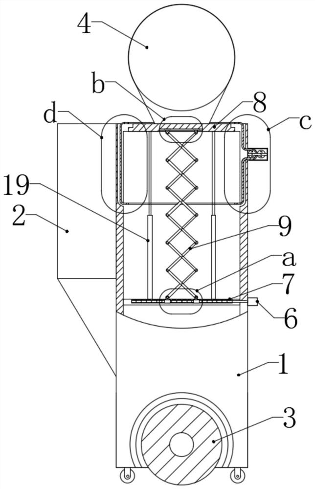
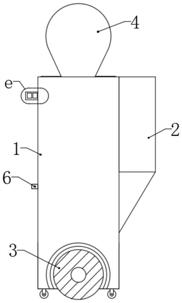
[0033] refer to Figure 1-9 , an intelligent teaching assistant robot with protection function, comprising a rear body 1, a front body 2, electric wheels 3, a head 4, and a display 5, and the front body 2 is installed on one side of the rear body 1 , and close to its upper side, there are two electric wheels 3, and they are all installed on the bottom wall of the rear body 1, and there are two displays 5, one is installed with the front body 2, and the other is connected with the head 4 installation, it is characterized in that the interior of the rear fuselage 1 is hollow, the interior of the rear fuselage 1 is fixed with a fixed plate 7 at the position on the lower side, and a two-way threaded rod 10 is provided for rotation in the fixed plate 7, and the two-way threaded rod One end of 10 extends to the outside of rear side fuselage 1 and first motor 6 is installed, and the bottom of head 4 is equipped with support plate 8, is installed between the bottom wall of support plate 8 and the top wall of two-way threaded rod 10 X-shaped cross lifting frame 9, the two ends of X-shaped cross lifting frame 9 are located at the lower side to be rotated with threaded blocks 11, and two threaded blocks 11 are symmetrically threaded on the two-way threaded rod 10, X-shaped crossed lifting frame 9 The two ends on the upper side are rotatably mounted with sliders 12, and the sliders 12 are slidably connected to the bottom wall of the support plate 8;
[0034] Each functional module of the robot can be installed on the underside of the rear body 1 and the inside of the front body 2, and its functional modules are in the prior art, and this solution does not involve the improvement of the existing functional modules.
[0035] On the upper side of the rear body 1 and away from the side of the front body 2, a cabinet 13 is installed. Two rollers 14 are installed in the cabinet 13, and the rotating shafts of the rollers 14 all extend to the outside of the cabinet 13 and the first Two motors 18, two second motors 18 are all fixed to the outer side wall of the cabinet 13, and the inside of the board body of the rear side body 1 is provided with an empty slot 15, and the upper side of the empty slot 15 extends out of the upper end of the rear side body 1, A protective belt 16 is provided in the empty slot 15 and the casing 13. The protective belt 16 is closed end to end. A section of the protective belt 16 located in the casing 13 is in contact with the roller surfaces of the two rollers 14 at the same time. The protective belt 16 is symmetrically opened up and down. There are two notches 17 , the size of which is larger than the size of the head 4 and the support plate 8 .
[0036] The head 4 is spherical, the support plate 8 is circular, and the diameter of the support plate 8 is not smaller than the diameter of the head 4 .
[0037] The notch 17 is circular or square, and the inner diameter of the notch 17 is not smaller than the diameter of the support plate 8 . The notch 17 corresponds to the support plate 8. When the head 4 and the support plate 8 are raised, they can pass through the two notches 17 from bottom to top. Finally, the head 4 stands completely above the rear body 1, and the support plate 8 coincides with the top of the rear body 1.
[0038] The X-shaped cross lifting frame 9 is made up of a plurality of X-shaped cross bars that are rotated from end to end, and each X-shaped cross bar is made up of two bar bars that are rotated and installed in the middle by pivot pins.
[0039] Between the top wall of the two-way threaded rod 10 and the bottom wall of the support plate 8, a plurality of telescopic rods 19 are symmetrically installed, and the telescopic rods 19 are composed of a plurality of slidingly connected sleeves and sub-rods.
[0040] The first motor 6 is a servo motor, and its input end is connected to the single-chip microcomputer, and the two second motors 18 are also connected to the single-chip microcomputer. The single-chip microcomputer controls the first motor 6 to realize forward rotation and reverse rotation.
[0041]The model of the single-chip microcomputer is a programmable 89S51 type, and the single-chip microcomputer is installed on the lower side of the rear side fuselage 1 bottom, and the rear side fuselage 1 has a built-in rechargeable storage battery. In addition, the robot can also be electrically connected to an external power supply through a power cord.
[0042] The bottom wall of the rear fuselage 1 is also equipped with two universal wheels. The straight line where the two universal wheels are and the straight line where the two electric wheels 3 are perpendicular to each other. The universal wheels are used for the support of the robot body, and at the same time, it is convenient for the robot to maintain stability when turning.
[0043] The working principle and application process of the present invention: the robot moves through the electric wheels 3 at the bottom, and the two electric wheels 3 are independent of each other, and can be rotated at the same time or independently. Turning can be realized when rotating alone, and forward or backward can be realized when rotating simultaneously .
[0044] When the robot is idle, the first motor 6 drives the vertical threaded rod 10 to rotate. At this time, the two-way threaded rod is threadedly connected with the two threaded blocks 11 installed at the bottom of the X-shaped cross lifting frame 9, so that the two threaded blocks 11 are away from each other. , at this time, the height of the X-shaped cross lifting frame 9 can be reduced or contracted. At this time, the support plate 8 and the head 4 can be pulled down to the inside of the rear chassis 1. When the head 4 completely enters the rear chassis 1 , the first motor 6 stalls; at this time, two second motors 18 simultaneously and reversely drive the roller 14 to rotate (reverse reference Figure 7 As shown by the arrow in the figure, the roller 14 on the left side rotates clockwise, and the roller 14 on the right side rotates counterclockwise), the two rollers 14 impel the protective belt 16 to move, and the positions of the two gaps 17 are moved to make the gap 17 left figure 2 and Figure 7 In the initial position, the upper side of the rear side frame 1 is covered by the protective belt 16, the inside of the rear side frame 1 is protected, and the air is prevented from entering the inside.
[0045] The above is only a preferred embodiment of the present invention, but the scope of protection of the present invention is not limited thereto, any person familiar with the technical field within the technical scope disclosed in the present invention, according to the technical solution of the present invention Any equivalent replacement or change of the inventive concepts thereof shall fall within the protection scope of the present invention.