
A drawing frame cleaning device

A technology of cleaning device and drawing frame, applied in spinning machine, textile and paper making, drafting equipment, etc. The effect of uniform conveying, avoiding clutter and knotting, and improving the centering effect

Active Publication Date: 2021-11-26
李秀铅
View PDF5 Cites 0 Cited by
  • Summary
  • Abstract
  • Description
  • Claims
  • Application Information

AI Technical Summary

Problems solved by technology

[0004] The main purpose of the present invention is to overcome the deficiencies of the prior art, and provide a drawing frame cleaning device to solve the problem of abnormal rotation of the conveying double rollers, uneven conveying speed, loosening and tightness of the sliver, and improper control of the air suction volume, causing the sliver to be scattered. , easy to knot and break away from the thread position, if the flying flowers and dust are not absorbed in time to make them fall on the sliver, it will cause more serious problems of slivers and knots

Method used


Image

  • A drawing frame cleaning device
  • A drawing frame cleaning device
  • A drawing frame cleaning device

Examples


Embodiment 1

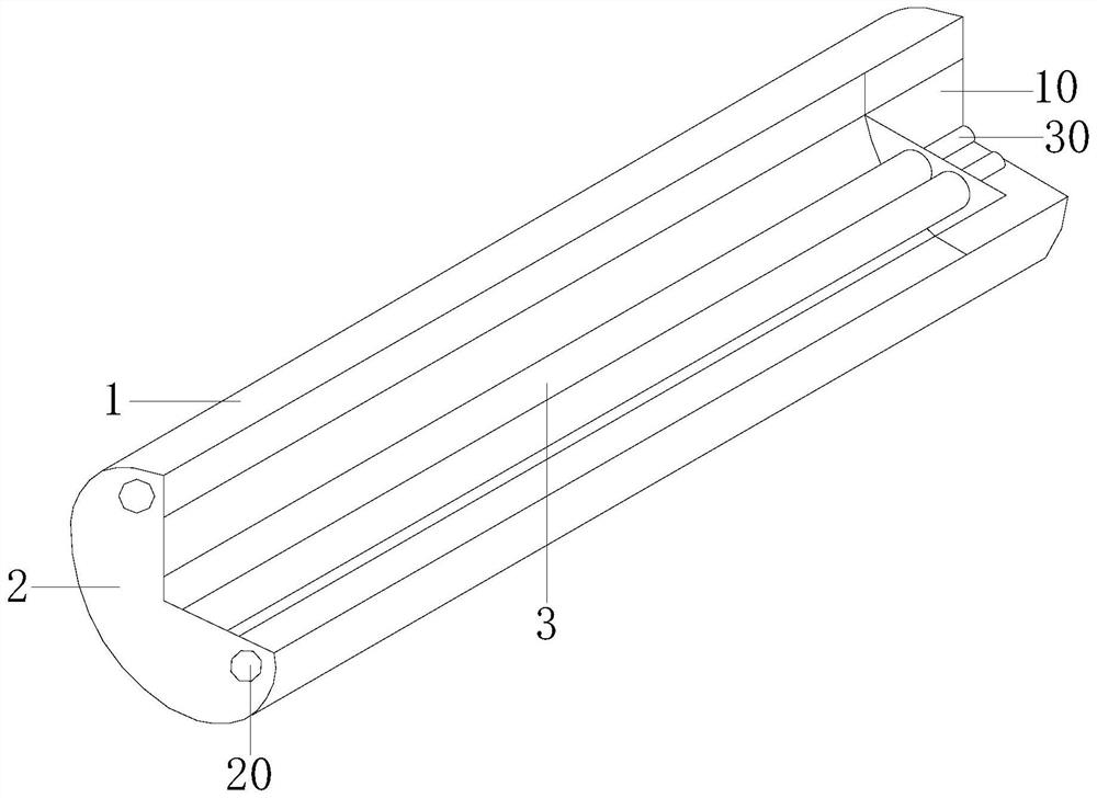
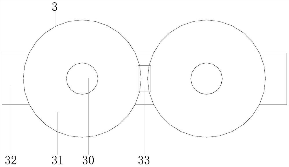
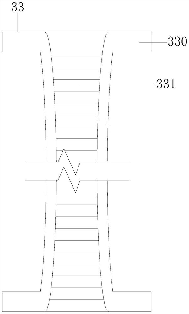
[0026] Example 1 see Figure 1-4 , the present invention provides a technical solution for a drawing frame cleaning device: its structure includes a dust collecting frame 1, a side mounting plate 2, and a conveying double roller 3, the dust collecting frame 1 is installed and connected to the side mounting plate 2, and the conveying double The roller 3 is installed on the dust collection frame 1 and the side mounting plate 2, the dust collecting frame 1 is equipped with a thickened side plate 10, the side mounting plate 2 is provided with a locking shaft 20, the thickened side plate 10, The locking shaft 20 is located at the left and right ends of the conveying double rollers 3. The conveying double rollers 3 include a rod shaft 30, a transmission line double roller 31, a mounting plate 32, and a middle device 33. The rod shaft 30 and the transmission line double rollers 31 Shaft connection, the double rollers 31 of the transmission line are attached to the middle device 33, t...

Embodiment 2

[0028] Example 2 see Figure 5-7 , the present invention provides a technical solution for a drawing frame cleaning device: the structure of the end center line device 50 includes a spring cover frame 500, a center line end spring 501, a center line side end plate 502, and a wire storage plate 503, and the end center line The device 50 plays the role of controlling the conveying speed of the sliver. The spring cover frame 500 is welded with the midline end spring 501, and the spring cover frame 500 is installed and connected with the midline side end plate 502. The plate 503 is installed and connected, and the elastic force of the center line end spring 501 plays a role in supporting the line storage plate 503 so that it fits with the sliver. The middle line device 51 includes an end plate 510 and a main delivery plate 511. The end plate 510 is assembled and connected with the main feeding board 511, and the main feeding board 511 includes the side board 5110, the middle board...


PUM


Abstract

The invention discloses a drawing frame cleaning device, the structure of which comprises a dust collecting frame, a side mounting plate, and conveying double rollers, the dust collecting frame and the side mounting plate are installed and connected, and the conveying double rollers are installed on the dust collecting frame and the side mounting plate , the dust collection rack is equipped with thickened side plates, and the side plate is equipped with a lock shaft, the thickened side plate and the lock shaft are located at the left and right ends of the double conveying rollers, and the conveying double rollers include rod shafts, transmission line double rollers, mounting The plate and the middle device, the rod shaft is connected with the double roller shaft of the transmission line, the double rollers of the transmission line are attached to the middle device, the rod shaft and the middle device are installed on the mounting plate, and the middle device includes an embedded roller frame, a wire groove device, and an embedded roller frame Installed and connected with the wire groove device, the cotton sliver of the present invention is fed from the middle device, that is, fed from the wire groove device, and is located in the middle of the wire feeding structure. The uniform speed of the sliver conveying ensures that the sliver is moderately elastic, reasonably centered and not scattered, and prevents the sliver from being scattered and knotted due to the adhesion of flying flowers and dust.

Description

technical field [0001] The invention relates to the field of textile equipment, in particular to a drawing frame cleaning device. Background technique [0002] The function of the cleaning device is to remove the flying flowers and dust attached to the surface of the equipment in time. It adopts suction cleaning to clean the flying flowers and dust, and sucks them into the dust filter box through suction to achieve the effect of smooth transportation of textile threads without knotting. [0003] In the prior art, the double rollers of conveying are abnormally rotated, the conveying speed is uneven, the sliver will be loose and tight sometimes, and the air suction volume is not properly controlled. On the sliver it can cause more serious loosening and knotting of the sliver. Contents of the invention [0004] The main purpose of the present invention is to overcome the deficiencies of the prior art, and provide a drawing frame cleaning device to solve the problem of abnorm...

Claims


Application Information

Patent Timeline
Patent Type & Authority Patents(China)
IPC IPC(8): D01H5/66D01H13/04
CPCD01H5/66D01H13/04
Inventor 张智强李秀铅
Owner 李秀铅
Learn More