
Automatic cutting-off device in textile fabric winding process

A technology for automatic cutting and weaving of fabrics, applied in textiles and papermaking, knitting, weft knitting, etc., can solve the problems of fabric cutting, affecting fabric quality, and low efficiency of fabric winding, and achieve a neat cutting effect

Inactive Publication Date: 2020-12-11
梁春惠
View PDF9 Cites 4 Cited by
  • Summary
  • Abstract
  • Description
  • Claims
  • Application Information

AI Technical Summary

Problems solved by technology

[0003] In the process of rewinding the textile fabric, the fabric cannot be cut automatically, and during the cutting process, the fabric cannot be automatically stopped from rewinding, resulting in scratches on the surface of the textile fabric, and the fabric rewinding efficiency is low. At the same time, after cutting, a large number of Fine hair and wadding are easy to stick to the cutting surface, which affects the quality of the fabric. Therefore, in view of this, research and improvement are made on the existing structure and defects, and an automatic cutting device for the textile fabric winding process is provided in order to achieve more practical value. sexual purpose

Method used

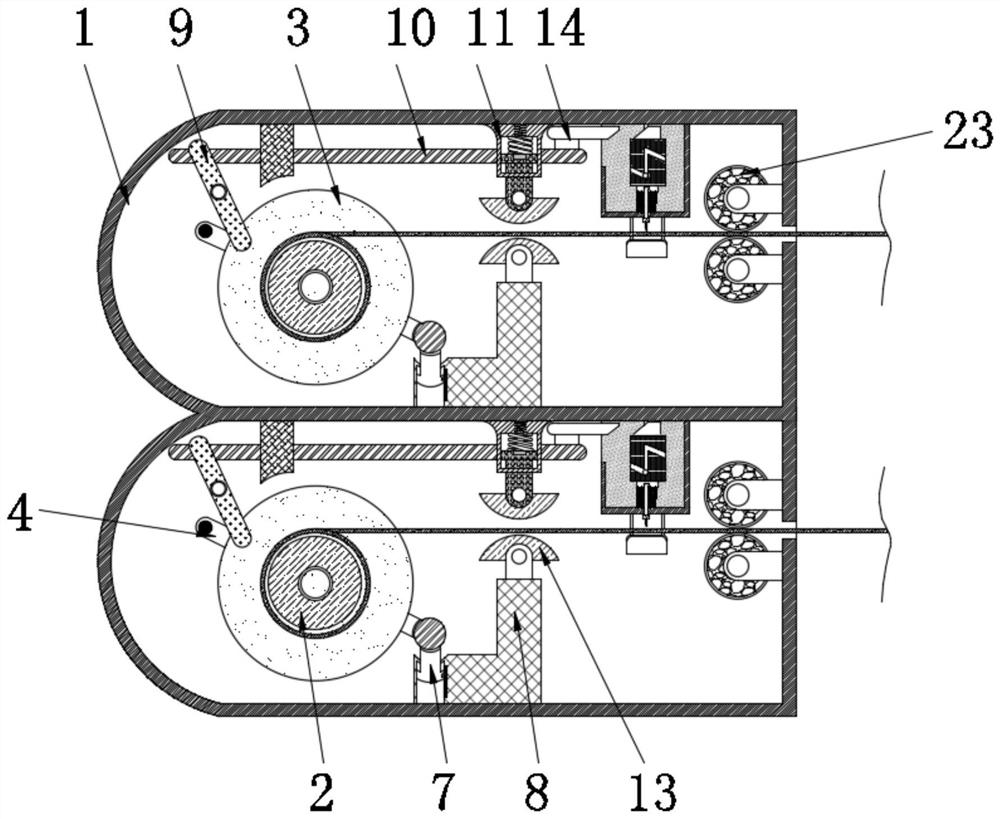
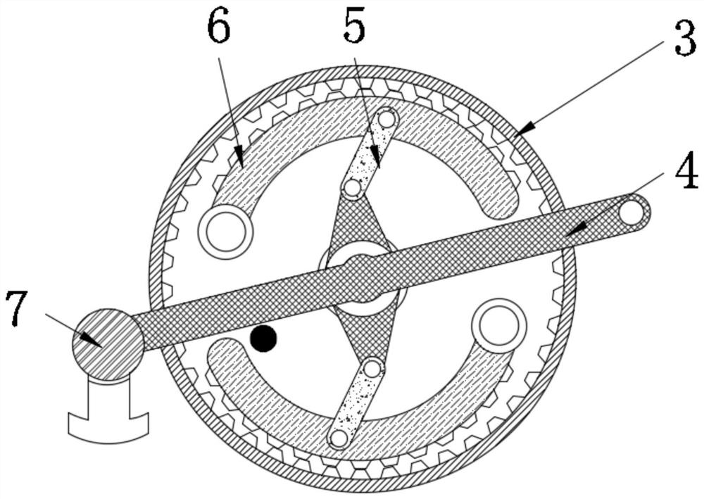
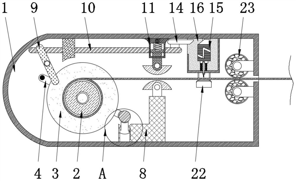

Image

  • Automatic cutting-off device in textile fabric winding process
  • Automatic cutting-off device in textile fabric winding process
  • Automatic cutting-off device in textile fabric winding process

Examples


Embodiment Construction

[0022] The present invention will be further described below in conjunction with accompanying drawing:

[0023] The invention provides an automatic cutting device in the winding process of textile cloth, as attached figure 1 to attach Figure 6 Shown: includes the processing chamber 1, the inner rotation of the processing chamber 1 is installed with the winding roller 2, and the rear surface of the winding roller 2 is fixedly installed with the disc 3, and the diameter of the disk 3 is larger than the diameter of the winding roller 2. The interior of the adjustment rod 4 is provided with an adjusting rod 4, the upper and lower surfaces of the adjusting rod 4 are movably connected with an auxiliary rod 5, and the auxiliary rod 5 is movably installed on the surface of the card frame 6, and the surface of the card frame 6 and the inner wall of the disc 3 are provided with corresponding The gear block, the card frame 6 is an arc-shaped structure, the right end of the adjustment r...


PUM


Abstract

The invention provides an automatic cutting-off device in a textile fabric winding process. A round wheel is slidably mounted in a mounting plate, an inclined groove is formed in the surface of the round wheel, a bottom block is mounted at the bottom of the round wheel through a rolling bearing, and a compression spring is fixedly connected between the lower surface of the bottom block and the lower wall of the interior of the mounting plate; and connecting rods are fixedly mounted on the front surface and the rear surface of the bottom block, and a cutter is fixedly mounted between every twoadjacent connecting rods. The diameter of a fabric on the outer surface of a winding roller is larger and larger, thus a movable rod is driven to move leftwards, based on a lever principle, the movable rod drives a transverse rod to slide rightwards in a top seat, when the push block moves rightwards, the round wheel is pressed by an inclined face to move downwards in the mounting plate, meanwhile, through design of the inclined groove and a protruding column, the round wheel is driven to rotate clockwise by a certain distance, the connecting rod on the lower surface of the bottom block and the cutters are driven to move downwards together, the textile fabric is cut off on the upper surface of a cutter holder, and therefore the purpose of automatic cutting in the winding process is achieved.

Description

technical field [0001] The invention belongs to the technical field of textile processing, and in particular relates to an automatic cutting device in the winding process of textile cloth. Background technique [0002] Textile fabrics are often made of low-elastic polyester yarns or special-shaped polyester yarns, nylon yarns, cotton yarns, wool yarns, etc., and are woven on various weft knitting machines. After the fabrics are produced, they need to be rolled up. The fabric needs to be cut. [0003] In the process of rewinding the textile fabric, the fabric cannot be cut automatically, and during the cutting process, the fabric cannot be automatically stopped from rewinding, resulting in scratches on the surface of the textile fabric, and the fabric rewinding efficiency is low. At the same time, after cutting, a large number of Fine hair and wadding are easy to stick to the cutting surface, which affects the quality of the fabric. Therefore, in view of this, research and i...

Claims


Application Information

Patent Timeline
Patent Type & Authority Applications(China)
IPC IPC(8): D04B15/88D04B35/34D06C25/00
CPCD04B15/88D04B35/34D06C25/00
Inventor 梁春惠
Owner 梁春惠
Learn More