
Plate-fin heat exchanger for steam waste heat recovery device

A technology of plate-fin heat exchanger and recovery device, which is applied in the direction of indirect heat exchanger, heat exchanger type, heat exchange equipment, etc. It can solve the problems of reducing the use effect of the device, leaving residues in the filter, and difficult cleaning by the operator. problem, achieve the effect of reducing impact, convenient cleaning, and avoiding filter effect

Inactive Publication Date: 2020-12-11
广州万可科技有限公司
View PDF0 Cites 0 Cited by
  • Summary
  • Abstract
  • Description
  • Claims
  • Application Information

AI Technical Summary

Problems solved by technology

[0002] Plate-fin heat exchangers are usually composed of partitions, fins, seals, and deflectors. Fins, deflectors, and seals are placed between two adjacent partitions to form a sandwich, which is called a channel. Such an interlayer According to the different ways of the fluid, they are stacked and brazed into a whole to form a plate bundle. The plate bundle is the core of the plate-fin heat exchanger; the plate-fin heat exchanger used in the steam waste heat recovery device currently on the market requires First pass the steam through the partition, and then recover the waste heat of the steam; in the prior art, due to the long-term filtration of the particulate matter in the steam, residues are easily left on the filter screen, making it difficult for the operator to clean it, thus reducing the efficiency of the device. The effect of using

Method used


Image

  • Plate-fin heat exchanger for steam waste heat recovery device
  • Plate-fin heat exchanger for steam waste heat recovery device
  • Plate-fin heat exchanger for steam waste heat recovery device

Examples


Embodiment Construction

[0049] The following will clearly and completely describe the technical solutions in the embodiments of the present invention with reference to the accompanying drawings in the embodiments of the present invention. Obviously, the described embodiments are only some, not all, embodiments of the present invention. Based on the embodiments of the present invention, all other embodiments obtained by persons of ordinary skill in the art without making creative efforts belong to the protection scope of the present invention.

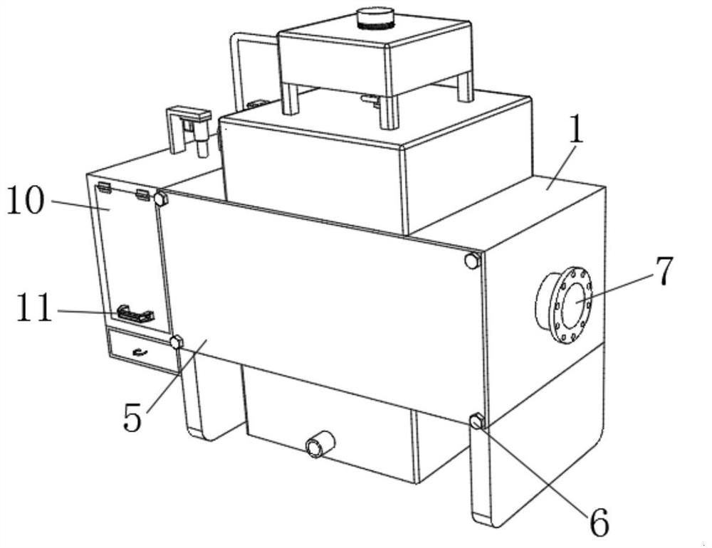
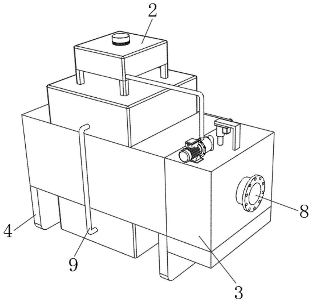
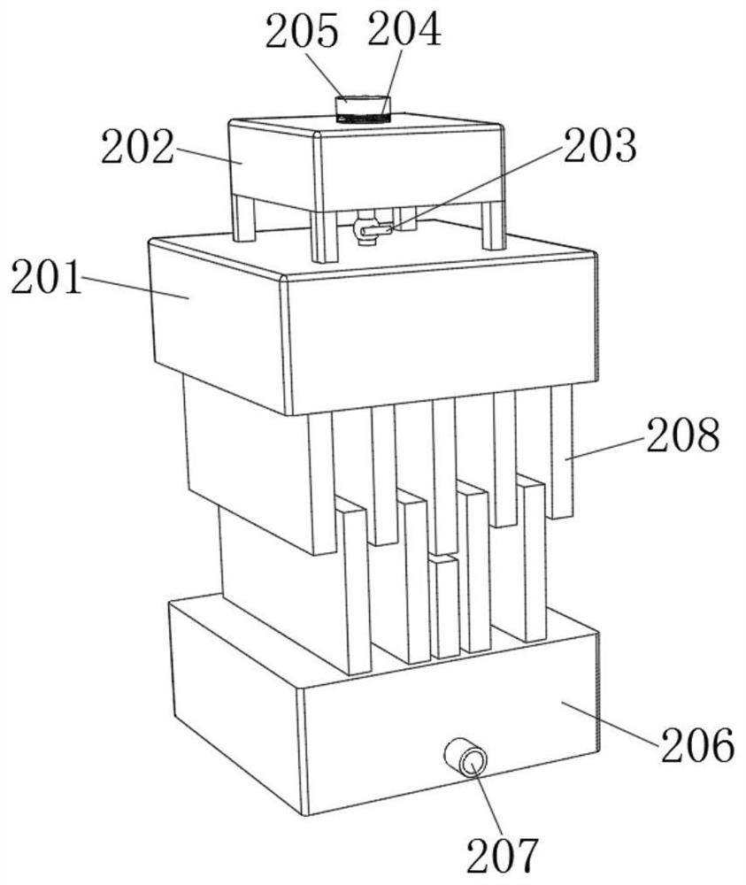
[0050] see Figure 1-5 , the present invention provides a technical solution: a plate-fin heat exchanger for a steam waste heat recovery device, including a treatment box 1, a heat absorbing device 2 is fixedly connected to the middle of the outer surface of the treatment box 1, and the left side of the treatment box 1 The treatment device 3 is fixedly connected, the left and right sides of the lower surface of the treatment box 1 are fixedly connected with a ...


PUM


Abstract

The invention relates to the technical field of heat exchangers, and discloses a plate-fin heat exchanger for a steam waste heat recovery device. The heat exchanger comprises a treatment box; a heat absorption device is fixedly connected with the middle part of the outer side surface of the treatment box; a treatment device is fixedly connected with the left side surface of the treatment box; andsupporting plates are fixedly connected with the left and right sides of the lower surface of the treatment box. According to the plate-fin heat exchanger for the steam waste heat recovery device, bystarting a push rod motor, a moving frame moves downwards to drive a water spraying pipe to move downwards, and the water spraying pipe moves downwards to clean a treatment layer, so that the phenomenon that particle matter adheres to the surfaces of parts and is difficult to clean is prevented, the effect that an operator operates the device to clean the parts is improved, the operator can cleanthe surfaces of the parts more conveniently, the situation that the filtering effect of the heat exchanger is reduced due to the adhesion of the particle matter is avoided, and the influence on normaluse of the heat exchanger is reduced.

Description

technical field [0001] The invention relates to the technical field of heat exchangers, in particular to a plate-fin heat exchanger for a steam waste heat recovery device. Background technique [0002] Plate-fin heat exchangers are usually composed of partitions, fins, seals, and deflectors. Fins, deflectors, and seals are placed between two adjacent partitions to form a sandwich, which is called a channel. Such an interlayer According to the different ways of the fluid, they are stacked and brazed into a whole to form a plate bundle. The plate bundle is the core of the plate-fin heat exchanger; the plate-fin heat exchanger used in the steam waste heat recovery device currently on the market requires First pass the steam through the partition, and then recover the waste heat of the steam; in the prior art, due to the long-term filtration of the particulate matter in the steam, it is easy to leave residue on the filter screen, which makes it difficult for the operator to clea...

Claims


Application Information

Patent Timeline
Patent Type & Authority Applications(China)
IPC IPC(8): F28D9/00F28F19/01F28F27/00B01D46/12B01D46/00
CPCF28D9/0081F28F19/01F28F27/00B01D46/12B01D46/72
Inventor 周丹华
Owner 广州万可科技有限公司
Learn More