A vertically wound flat transformer
A transformer and flat technology, which is applied in the field of vertical winding flat transformers, can solve the problems of inconvenient use of transformers, and achieve the effect of ease of use
- Summary
- Abstract
- Description
- Claims
- Application Information
AI Technical Summary
Problems solved by technology
Method used
Image

Examples
specific Embodiment approach 1
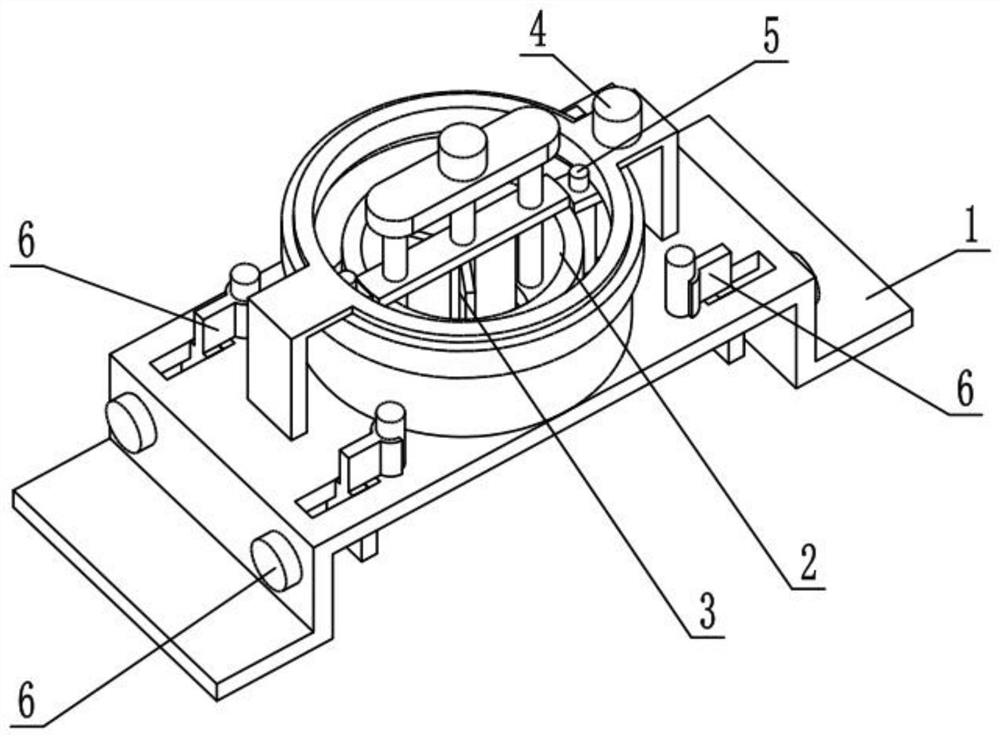
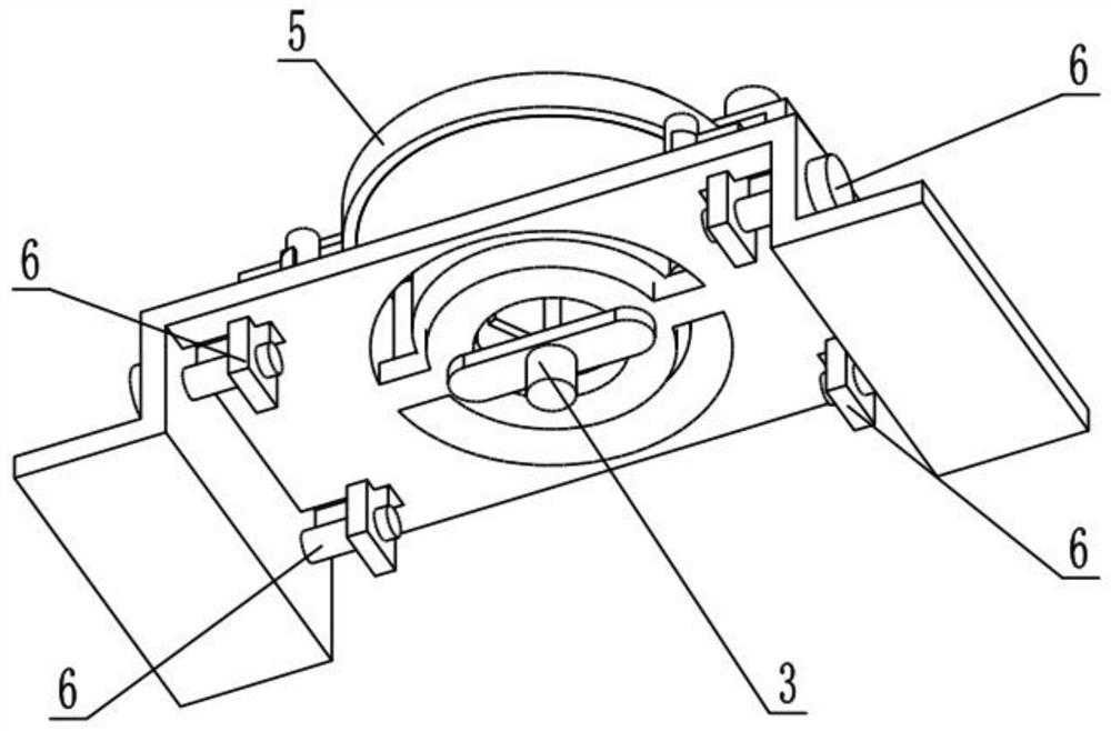
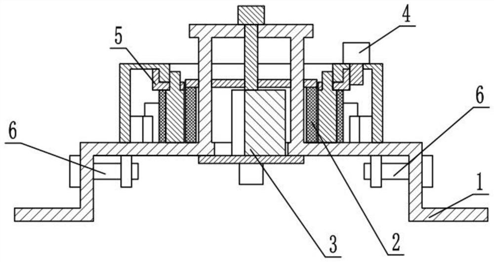
[0027] Such as Figure 1-9 As shown, a vertically wound flat transformer includes a primary coil mechanism 1, a secondary coil mechanism 2, a central heat dissipation mechanism 3, a support frame mechanism 4, a rotating heat dissipation mechanism 5, and a wiring mechanism 6. The secondary coil mechanism 2 Connected in the primary coil mechanism 1, the central cooling mechanism 3 is fixedly connected to the lower end of the primary coil mechanism 1 and located in the secondary coil mechanism 2, and the support frame mechanism 4 is fixedly connected to the primary coil mechanism 1, so The above-mentioned rotating cooling mechanism 5 is rotatably connected to the supporting frame mechanism 4, and the supporting frame mechanism 4 and the rotating cooling mechanism 5 are connected by transmission. There are four wiring mechanisms 6, and the four wiring mechanisms 6 are all connected to the primary coil mechanism. 1 on.
[0028] When in use, when the input voltage is constant and t...
specific Embodiment approach 2
[0029] Such as Figure 1-9 As shown, the primary coil mechanism 1 includes a primary coil body 1-1, a mounting plate 1-2, an inner ring plate 1-3, a leg mounting plate 1-4, a slide hole 1-5, and a terminal post 1-6 , lifting sliding column 1-7 and fixed plate 1-8, the primary coil body 1-1 is fixedly connected to the mounting plate 1-2, and the inner ring plate 1-3 is fixedly connected to the mounting plate 1-2 and is located on the primary coil body In 1-1, there are two outrigger mounting plates 1-4, and the two outrigger mounting plates 1-4 are symmetrically fixedly connected to both ends of the mounting plate 1-2, the sliding holes 1-5 and the terminal posts 1-6 All are provided with four, four sliding holes 1-5 are respectively arranged at the four corners of the mounting plate 1-2, and the four terminal posts 1-6 are respectively fixedly connected at the four corners of the mounting plate 1-2, and the lifting sliding column 1- 7 is provided with two, and the two lifting...
specific Embodiment approach 3
[0030] Such as Figure 1-9 As shown, the secondary coil mechanism 2 includes a secondary coil body 2-1, a coil connecting plate 2-2, a threaded rod I2-3 and an adjustment knob I2-4, and the upper end of the secondary coil body 2-1 is fixedly connected to There is a coil connection plate 2-2, the secondary coil body 2-1 is located in the primary coil body 1-1, the coil connection plate 2-2 is slidably connected to the two lifting sliding columns 1-7, and the threaded rod Ⅰ2-3 passes through the thread Connected to the coil connection plate 2-2, the adjustment knob I2-4 is fixedly connected to the upper end of the threaded rod I2-3, the threaded rod I2-3 is connected to the fixed plate 1-8 in rotation, the secondary coil body 2-1 is connected to two of them Two terminal posts 1-6 are connected, and the primary coil body 1-1 is connected with the other two terminal posts 1-6.
[0031] The primary coil body 1-1 is electrically connected through two terminal posts 1-6 to generate ...
PUM
 Abstract
Description
Claims
Application Information
 - R&D
- Intellectual Property
- Life Sciences
- Materials
- Tech Scout
- Unparalleled Data Quality
- Higher Quality Content
- 60% Fewer Hallucinations
Browse by: Latest US Patents, China's latest patents, Technical Efficacy Thesaurus, Application Domain, Technology Topic, Popular Technical Reports.
© 2025 PatSnap. All rights reserved.Legal|Privacy policy|Modern Slavery Act Transparency Statement|Sitemap|About US| Contact US: help@patsnap.com