Automatic flying bar assembly assembling machine and assembling method thereof

An assembly machine and flying rod technology, applied in electrical components, waveguide devices, circuits, etc., can solve the problems of low production efficiency and high labor costs, and achieve the effects of reducing labor costs, high automation, and simple and reliable structure.

Active Publication Date: 2020-12-11
中山市川上智能设备有限公司
View PDF9 Cites 0 Cited by
  • Summary
  • Abstract
  • Description
  • Claims
  • Application Information

AI Technical Summary

Problems solved by technology

[0002] The fly rod assembly is an important part of the filter. It is formed by pressing the fly rod and the fly rod seat. The existing pressing method is to manually press the fly rod and the fly rod seat into the jig respectively. After pressing, manually put the flying rod assembly in the jig into the hole of the carrier substrate, and then start the next pressing, the production efficiency is low and the labor cost is high

Method used


Image

  • Automatic flying bar assembly assembling machine and assembling method thereof
  • Automatic flying bar assembly assembling machine and assembling method thereof
  • Automatic flying bar assembly assembling machine and assembling method thereof

Examples


Embodiment Construction

[0035] The technical features of the present invention will be described in further detail below in conjunction with the accompanying drawings so that those skilled in the art can understand.

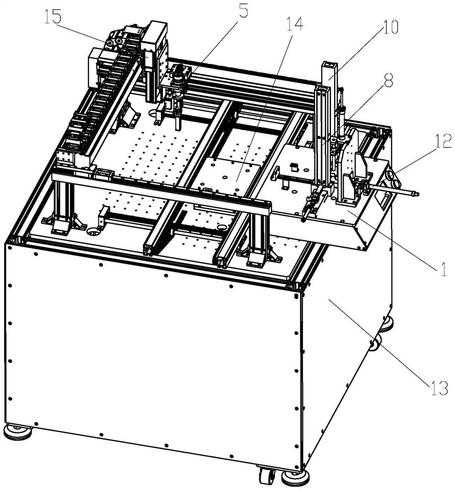
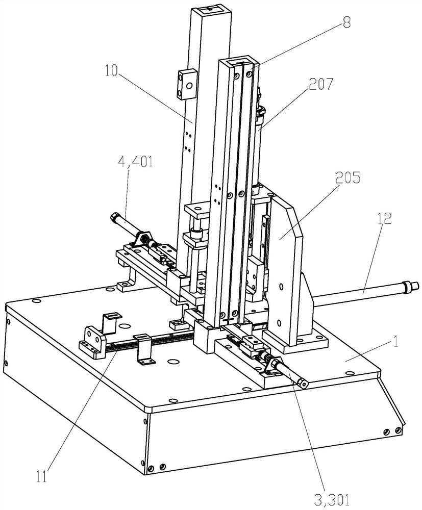
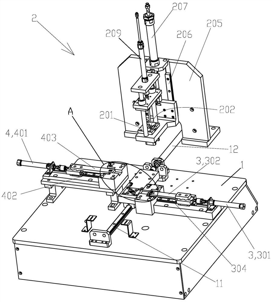
[0036] An automatic assembly machine for fly rod components, such as Figure 1 to Figure 9As shown, a mounting table 1 is included, and a first vertical track 8 for feeding the flying rod 6, a second vertical rail 10 for feeding the flying rod seat 7, and a A fourth slide rail 11 is respectively provided between the first vertical rail 8 and the second vertical rail 10, a first slide plate 9 is slidably provided on the fourth slide rail 11, and an assembly assembly is arranged on the first slide rail 9. The hole 901 is provided with the first pushing device 3 passing through the bottom of the first vertical rail 8 and pushing the flying rod 6 dropped on the first vertical rail 8 to the assembly hole 901 on the mounting table 1, the flying rod 6 falls from the first pushing device 3 to ...


PUM


Abstract

The invention discloses an automatic flying bar assembly assembling machine and an assembling method thereof. According to the technical scheme, the automatic flying bar assembly assembling machine ischaracterized in that the automatic flying bar assembly assembling machine comprises a mounting table; a first vertical rail and a second vertical rail are arranged on the mounting table; a fourth sliding rail is arranged between the first vertical rail and the second vertical rail; a first sliding plate is arranged on the fourth sliding rail in a sliding mode; an assembling hole is formed in thefirst sliding plate; a first pushing device and a press-in device are arranged on the mounting table; the press-in device is arranged above the first sliding plate and comprises a pressing block, a straight-through hole directly communicated with the assembling hole is formed in the pressing block, a second pushing device is arranged on the mounting table, and the flying bar base further falls into the assembling hole from the straight-through hole; the press-in device further comprises a first push rod which penetrates through the straight-through hole to press the fly rod base and the fly rod in the assembling hole into a fly rod assembly. The structure is simple and reliable, the automation degree is high, the production efficiency can be greatly improved, and the labor cost is reduced.

Description

【Technical field】 [0001] The invention relates to an automatic assembly machine for a fly rod assembly and an assembly method thereof. 【Background technique】 [0002] The fly rod assembly is an important part of the filter. It is formed by pressing the fly rod and the fly rod seat. The existing pressing method is to manually press the fly rod and the fly rod seat into the jig respectively. After pressing, manually put the fly rod assembly in the jig into the hole of the carrier substrate, and then start the next pressing, the production efficiency is low, and the labor cost is high. [0003] The present invention is made based on this situation. 【Content of invention】 [0004] The object of the present invention is to overcome the deficiencies of the prior art, and provide an automatic assembly machine for fly rod components and an assembly method thereof, which has a simple and reliable structure, can greatly improve production efficiency, and reduce labor costs. [000...

Claims


Application Information

Patent Timeline
IPC IPC(8): H01P11/00
CPCH01P11/007
Inventor 魏高军高峰磊李磊梁永康郭锐俊冯志辉郑永基邱茂荣
Owner 中山市川上智能设备有限公司
Why Eureka
Try Eureka