
Charging circuit and power terminal

A charging circuit and technology to be charged, applied in battery circuit devices, circuit devices, safety/protection circuits, etc., can solve the problems of reduced capacitance capacity, low utilization rate of supercapacitor capacity, shortened life, etc.

Active Publication Date: 2021-01-29
北京思凌科半导体技术有限公司
View PDF5 Cites 0 Cited by
  • Summary
  • Abstract
  • Description
  • Claims
  • Application Information

AI Technical Summary

Problems solved by technology

If the preset end-of-charge voltage is low, it will lead to the problem of low capacity utilization of the super capacitor; if the preset end-of-charge voltage is too high, overcharging will occur if the rated working voltage of the super capacitor is exceeded, resulting in a decrease in the capacity of the capacitor , the problem of shortened lifespan

Method used


Image

  • Charging circuit and power terminal
  • Charging circuit and power terminal
  • Charging circuit and power terminal

Examples


Embodiment Construction

[0033] Specific embodiments of the present disclosure will be described in detail below in conjunction with the accompanying drawings. It should be understood that the specific embodiments described here are only used to illustrate and explain the present disclosure, and are not intended to limit the present disclosure.

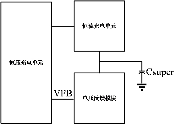
[0034] figure 1 It is a block diagram of a charging circuit in the related art shown according to an exemplary embodiment. Such as figure 1 As shown, the charging circuit may include a charging module and a voltage feedback module, wherein the charging module may further include a constant voltage charging unit and a constant current charging unit. The device to be charged may be a supercapacitor, a rechargeable battery, or any other device capable of constant current and constant voltage charging. exist figure 1 In , it is taken that the device to be charged is a supercapacitor Csuper as an example. The constant current charging unit is connected to one...


PUM


Abstract

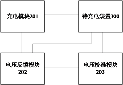
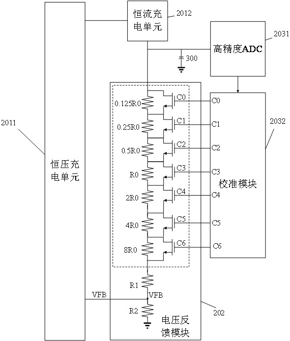
The disclosure relates to a charging circuit and a power terminal. The charging circuit includes: a charging module, a voltage feedback module, and a voltage calibration module, wherein the charging module, the voltage feedback module, and the voltage calibration module are respectively used to connect to a device to be charged, and the charging module and the voltage calibration module are respectively connected to the voltage feedback module; the voltage calibration module is used to obtain the first cut-off voltage of the device to be charged at the end of this charging, and determine the voltage of the voltage feedback module according to the first cut-off voltage and the preset target cut-off voltage Adjust the parameters, and adjust the voltage feedback module according to the adjusted parameters; the voltage feedback module is also used to generate a feedback signal based on the adjusted parameters and the voltage of the device to be charged during the next charging, so as to calibrate the termination voltage of the device to be charged. In this way, the accuracy of the cut-off voltage of the device to be charged is improved, and the capacity utilization rate of the device to be charged is improved as much as possible on the basis of no overshoot phenomenon.

Description

technical field [0001] The present disclosure relates to the technical field of charging, and in particular, to a charging circuit and a power terminal. Background technique [0002] In the broadband power line carrier HPLC communication module, it is necessary to use the supercapacitor charging and discharging management mechanism to realize the function of power outage reporting. Supercapacitor charging generally adopts the constant current (CC) constant voltage (CV) charging method. This method uses a constant high current charging at the initial stage of charging. When the capacitor voltage reaches the preset charging termination voltage, the charging current is reduced to zero, and To maintain the capacitor voltage at the preset end-of-charge voltage, that is, to switch from the constant current mode to the constant voltage mode. [0003] In the later stage of constant voltage charging, the preset charge termination voltage of the supercapacitor needs to be precisely c...

Claims


Application Information

Patent Timeline
Patent Type & Authority Patents(China)
IPC IPC(8): H02J7/00
CPCH02J7/0013H02J7/0029H02J7/0036H02J7/00302
Inventor 王本川
Owner 北京思凌科半导体技术有限公司
Learn More