
Three-phase motor stator and motor

A technology for three-phase motors and stators, applied to electrical components, electromechanical devices, electric components, etc., can solve the problems of winding loss on the surface of the stator, inconvenient access to the stator windings, etc.

Active Publication Date: 2020-12-11
苏州戈雷姆智能科技有限公司
View PDF4 Cites 0 Cited by
  • Summary
  • Abstract
  • Description
  • Claims
  • Application Information

AI Technical Summary

Problems solved by technology

[0004] The stator inside the three-phase motor in the prior art is fixed inside the motor casing, the rotor is plugged inside the stator, and then the rotor is squeezed through the end cover, so that the stator and rotor are fixed inside the casing, and when used for a long time The winding on the surface of the rear stator will be worn out, and the stator winding needs to be replaced. Since the stator is fixed inside the motor casing, it will cause the problem that the stator winding is inconvenient to take. The invention provides a three-phase motor stator and motor

Method used


Image

  • Three-phase motor stator and motor
  • Three-phase motor stator and motor
  • Three-phase motor stator and motor

Examples


Embodiment Construction

[0025] In order to make the technical means, creative features, goals and effects achieved by the present invention easy to understand, the present invention will be further described below in conjunction with specific embodiments.

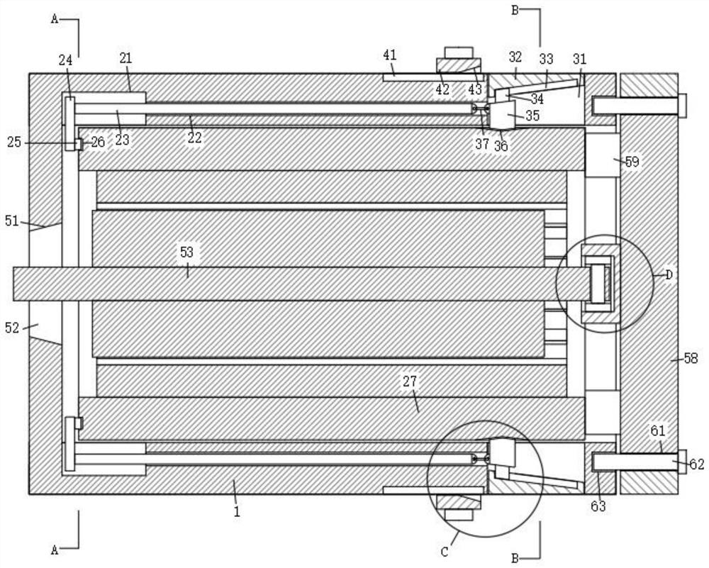
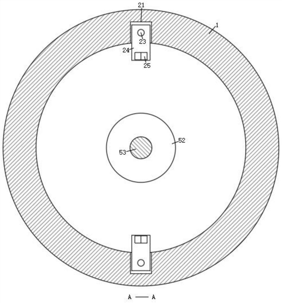
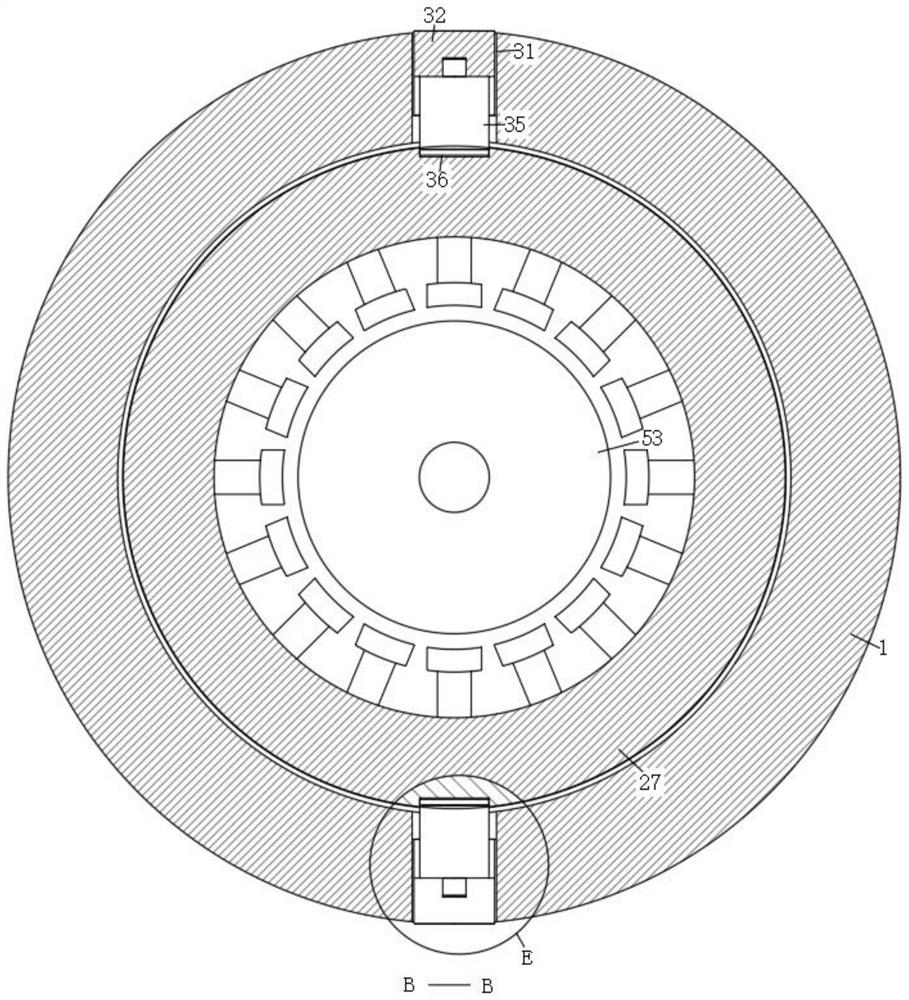
[0026] Such as Figure 1-Figure 7 As shown, a three-phase motor stator and motor according to the present invention include a casing 1, a stator mechanism 2 is arranged on the inner wall of the casing 1, a clamping mechanism 3 is arranged on the inner wall of the casing 1, and the casing 1 A pressing mechanism 4 is arranged on the outer wall of the casing 1 , a rotor mechanism 5 is arranged inside the casing 1 , and a fixing mechanism 6 is arranged on the surface of the rotor mechanism 5 .

[0027] Specifically, the stator mechanism 2 includes a chute 21, a socket 22, an insertion rod 23, a slide plate 24, a triangular block 25, a triangular slot 26, and a stator 27. One side wall of the two chutes 21 is provided with sockets 22, and the inside o...


PUM


Abstract

The invention relates to the technical field of motors, in particular to a three-phase motor stator and a motor, the three-phase motor stator comprises a casing, a stator mechanism arranged on the inner wall of the casing, a clamping mechanism is arranged on the inner wall of the casing, a pressing mechanism is arranged on the outer wall of the casing, a rotor mechanism is arranged inside the casing, and a fixing mechanism arranged on the surface of the rotor mechanism. The stator mechanism comprises a sliding groove, when a stator winding needs to be replaced, a bolt is rotated to enable thebolt to be separated from the interior of a threaded hole, fixing of a cover plate and a machine shell is relieved, then a trapezoidal block is pressed, an inclined block is pressed through an inclined groove in the surface of the trapezoidal block, and then the inclined block is driven to move and drives a clamping block to move. The clamping block drives the stator to move towards the opening ofthe casing through the triangular slot, the push rod drives the insertion rod to move, the insertion rod drives the sliding plate to move, and the sliding plate pushes the stator to move towards theopening of the casing, so that the stator is moved out of the casing, and the stator is prevented from being clamped in the casing and being inconvenient to take.

Description

technical field [0001] The invention relates to the technical field of motors, in particular to a three-phase motor stator and motor. Background technique [0002] Three-phase asynchronous motor is a kind of induction motor. It is a type of motor powered by 380V three-phase AC current at the same time. Since the rotor and stator of the three-phase asynchronous motor rotate in the same direction and at different speeds, there is Slip, so it is called a three-phase asynchronous motor. The speed of the rotor of the three-phase asynchronous motor is lower than the speed of the rotating magnetic field. The rotor winding generates electromotive force and current due to the relative motion between the rotor winding and the magnetic field, and interacts with the magnetic field to generate electromagnetic torque. , to achieve energy conversion. [0003] The stator inside the existing three-phase motor is fixed inside the motor casing, the rotor is plugged inside the stator, and then...

Claims


Application Information

Patent Timeline
Patent Type & Authority Applications(China)
IPC IPC(8): H02K1/12H02K1/18
CPCH02K1/12H02K1/185
Inventor 李电豹陈泽伟
Owner 苏州戈雷姆智能科技有限公司
Learn More