
Autonomous borrowing device

A technology for placing blocks and placing slots, which is applied in storage devices, identification devices, transportation and packaging, etc. It can solve problems such as bruising of borrowers, inconvenience of borrowing, and increase of borrowing time of borrowers, so as to save time, use conveniently, and facilitate The effect of taking

Pending Publication Date: 2021-12-17
SHANDONG FIRST MEDICAL UNIV & SHANDONG ACADEMY OF MEDICAL SCI
View PDF10 Cites 0 Cited by
  • Summary
  • Abstract
  • Description
  • Claims
  • Application Information

AI Technical Summary

Problems solved by technology

[0002] A library is an institution that collects, organizes, and collects books and materials for people to read and refer to. It is a memory device and diffusion device for social knowledge, information, and culture. Libraries exist in every city and every school for reading Borrowers, as time goes by, the stock of books in each library continues to increase. In order to facilitate storage and borrowing, different books will be classified and placed on different bookshelves. However, there are many problems for borrowers at present. : Due to the large number of books stored, the borrower cannot find the display position of the classified bookshelf of the books to be borrowed, and often needs to check one by one, which increases the borrowing time of the borrower and easily consumes the physical strength of the borrower; because the bookshelf The height is generally higher than that of the borrower. When picking up and storing books in a higher position, the borrower needs to stand on tiptoe or jump, which is easy to cause bruises to the borrower; when borrowing multiple books, it is not convenient for the borrower to search for a long time Take it, bring inconvenience to borrowing

Method used


Image

  • Autonomous borrowing device
  • Autonomous borrowing device
  • Autonomous borrowing device

Examples


Embodiment

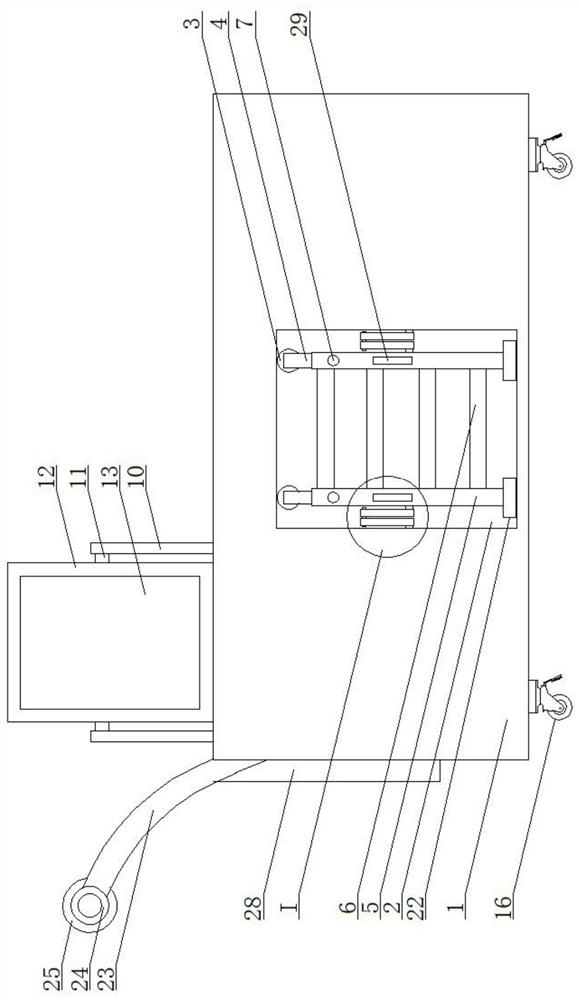
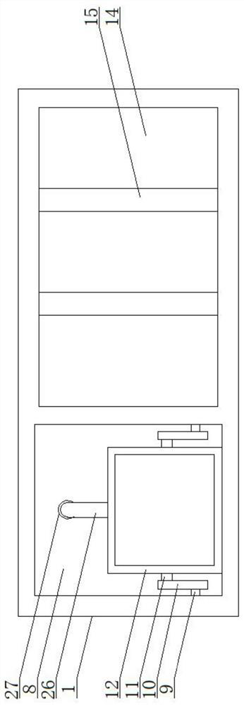
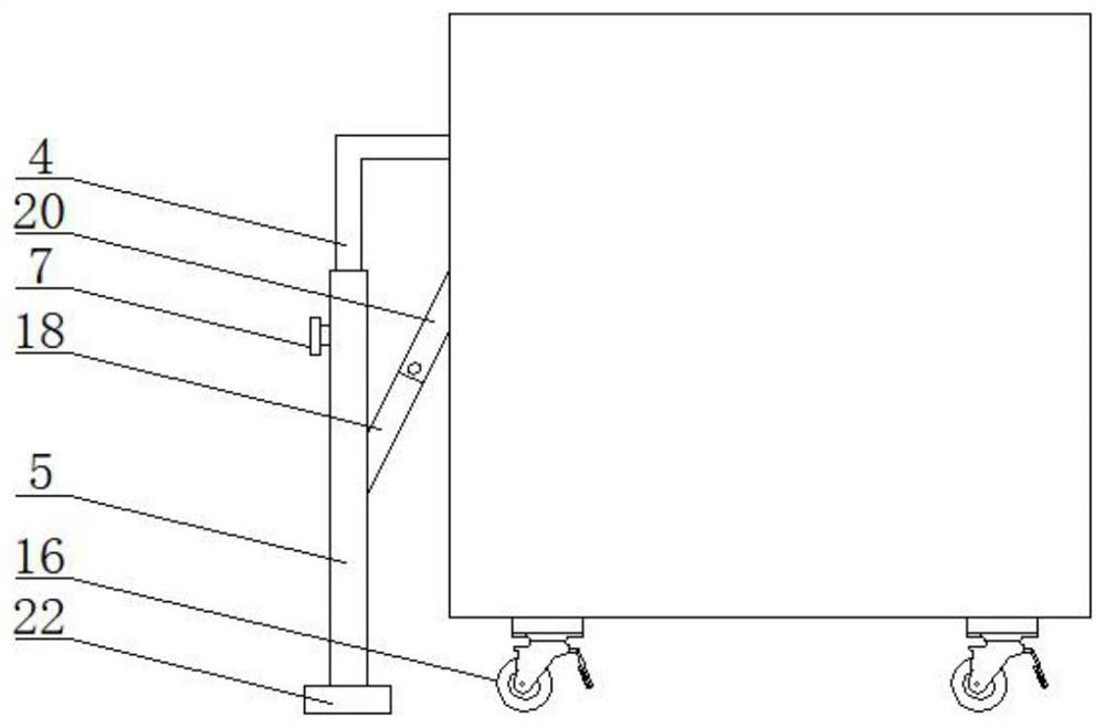
[0028] When using the device, first pull the vertical plate 12 upwards, and make the vertical plate 12 rotate around the second rotating shaft 11, while the vertical plate 12 rotates, the support rod 10 rotates around the first rotating shaft 9, and then pull the insertion rod 26 to make the insertion Rod 26 is inserted in the slot 27, and riser 12 is supported, and then the borrowing personnel checks the book storage table of contents 13 pasted on riser 12, looks for the storage location of the reading material that needs to borrow, then pulls this device, on universal wheel 16 The device is driven to move under the rolling motion, and then the reading material to be borrowed is taken and placed in the placement slot 14. When the reading material at a higher position needs to be taken, the vertical pipe 5 is pulled forward, and the vertical pipe 5 drives the L-shaped The rod 4 moves forward, and then the vertical pipe 5 slides downward along the L-shaped rod 4, so that the bot...


PUM


Abstract

The invention provides an autonomous borrowing device, and mainly relates to the field of book borrowing equipment. An autonomous borrowing device comprises a placing block, wherein a groove is formed in the front face of the placing block, two sleeves distributed left and right are installed in the groove, an L-shaped rod is slidably sleeved with each sleeve, a vertical tube is slidably sleeved with the bottom of each L-shaped rod, and a plurality of evenly-distributed transverse rods are installed between the two vertical tubes. Fastening rotary knobs are installed on the sleeves and the vertical tubes correspondingly, and a rectangular groove is formed in one side of the top face of the placing block. The book borrowing device has the advantages that the book borrowing device is simple in structure and convenient to use, borrowers can accurately and quickly find books to be borrowed conveniently by pasting a book storage catalog list on the vertical plate, the borrowers are prevented from looking for the books back and forth, the time of the borrowers is saved; and through cooperation of the supporting rod, the first rotating shaft and the second rotating shaft, the book storage catalog list can be turned into a rectangular groove, and the influence of the external environment on the book storage catalog list is avoided.

Description

technical field [0001] The invention mainly relates to the field of book lending equipment, in particular to an autonomous borrowing device. Background technique [0002] A library is an institution that collects, organizes, and collects books and materials for people to read and refer to. It is a memory device and diffusion device for social knowledge, information, and culture. Libraries exist in every city and every school for reading Borrowers, as time goes by, the stock of books in each library continues to increase. In order to facilitate storage and borrowing, different books will be classified and placed on different bookshelves. However, there are many problems for borrowers at present. : Due to the large number of books stored, the borrower cannot find the display position of the classified bookshelf of the books to be borrowed, and often needs to check one by one, which increases the borrowing time of the borrower and easily consumes the physical strength of the bo...

Claims


Application Information

Patent Timeline
Patent Type & Authority Applications(China)
IPC IPC(8): B65G1/04E06C9/08G09F3/00
CPCB65G1/04E06C9/08G09F3/00
Inventor 常强赵伟
Owner SHANDONG FIRST MEDICAL UNIV & SHANDONG ACADEMY OF MEDICAL SCI
Learn More