
A new energy vehicle charging pile with double charging guns

A technology for new energy vehicles and charging piles, applied in electric vehicle charging technology, electric vehicles, charging stations, etc., can solve the problems of shortening the service life of charging guns and affecting the charging of new energy vehicles.

Active Publication Date: 2021-12-28
HANGZHOU GUOKONG ELECTRIC TECH CO LTD
View PDF0 Cites 0 Cited by
  • Summary
  • Abstract
  • Description
  • Claims
  • Application Information

AI Technical Summary

Problems solved by technology

[0003] At present, there is a new energy vehicle charging pile with double charging guns. In order to facilitate the driver to take the chargers on both sides of the charging pile, the charging holster is usually scraped on both sides of the charging pile, which makes the charging gun exposed to the charging pile for a long time. Outside the pile, the charging gun will be exposed to wind and rain, which will shorten the service life of the charging gun, thus affecting the charging of new energy vehicles.

Method used


Image

  • A new energy vehicle charging pile with double charging guns
  • A new energy vehicle charging pile with double charging guns
  • A new energy vehicle charging pile with double charging guns

Examples


Embodiment 1

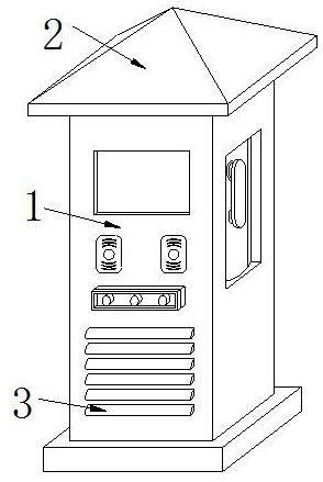
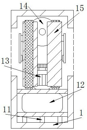
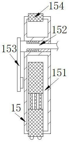
[0029] The present invention provides a charging pile for new energy vehicles with double charging guns. Its structure includes a charging pile 1, a ceiling 2, and a heat dissipation port 3. Located on the front side of the charging pile 1, the charging pile 1 includes a support plate 11, a storage box 12, a driver 13, a wire take-up 14, and a fixing block 15, and the support plate 11 is connected to the inner bottom of the charging pile 1 by welding, The battery box 12 is embedded on the upper surface of the support plate 11, the driver 13 is connected to the battery box 12, the wire take-up device 14 is connected to the inside of the charging pile 1 by bolts and is located above the driver 13, the fixed The block 15 is embedded and fixed on the left and right sides of the interior of the charging pile 1. The fixed block 15 is viewed as two symmetrical arc-shaped blocks, and the left and right sides of the charging pile 1 are provided with openings, and there are two wire take...

Embodiment 2

[0035]The present invention provides a charging pile for new energy vehicles with double charging guns. Its structure includes a charging pile 1, a ceiling 2, and a heat dissipation port 3. Located on the front side of the charging pile 1, the charging pile 1 includes a support plate 11, a storage box 12, a driver 13, a wire take-up 14, and a fixing block 15, and the support plate 11 is connected to the inner bottom of the charging pile 1 by welding, The battery box 12 is embedded on the upper surface of the support plate 11, the driver 13 is connected to the battery box 12, the wire take-up device 14 is connected to the inside of the charging pile 1 by bolts and is located above the driver 13, the fixed The block 15 is embedded and fixed on the left and right sides of the interior of the charging pile 1. The fixed block 15 is viewed as two symmetrical arc-shaped blocks, and the left and right sides of the charging pile 1 are provided with openings, and there are two wire take-...


PUM


Abstract

The invention discloses a new energy vehicle charging pile with double charging guns. Its structure includes a charging pile, a ceiling, and a cooling port. The bottom of the ceiling is connected to the top of the charging pile by welding, and the cooling hole is embedded in the front side of the charging pile. The beneficial effect is: put the charging gun back after charging, so that the charging cable is retracted inwardly under the winding of the wire take-up device. At this time, the limit spring pushes the push plate to support and limit the charging cable, and prevents the charging gun from being rolled into the take-up wire. At the same time, the scraper wipes the charging cable to prevent the charging cable from bringing external impurities into the charging pile. After storing the charging cable, start the driver, and drive the slider to slide under the engagement of the driver and the card slot, so that the partition The plate covers the outside of the charging gun to prevent the charging gun from being exposed to the outside world, so as to prevent the charging gun from being exposed to wind and rain, which will shorten the service life of the charging gun and affect the charging of new energy vehicles.

Description

technical field [0001] The invention relates to the field of charging piles, in particular to a new energy vehicle charging pile with double charging guns. Background technique [0002] With the development of the automobile industry, more and more new energy vehicles have entered our daily life. New energy vehicles use charging piles instead of refueling piles to charge the battery. Compared with other cars, they have less pollution to the environment and energy It has less waste and is widely used in the automotive industry. [0003] At present, there is a new energy vehicle charging pile with double charging guns. In order to facilitate the driver to take the chargers on both sides of the charging pile, the charging holster is usually scraped on both sides of the charging pile, which makes the charging gun exposed to the charging pile for a long time. Outside the pile, the charging gun will be exposed to wind and rain, which will shorten the service life of the charging ...

Claims


Application Information

Patent Timeline
Patent Type & Authority Patents(China)
IPC IPC(8): B60L53/31B60L53/16B65H75/44B65H75/48B08B1/02B08B1/20
CPCB60L53/31B60L53/16B65H75/48B65H75/44B08B1/165B08B1/20Y02T10/70Y02T10/7072Y02T90/12Y02T90/14
Inventor 易桃香
Owner HANGZHOU GUOKONG ELECTRIC TECH CO LTD
Learn More