Supercharge Your Innovation With Domain-Expert AI Agents!

Meissner effect test device

A test device and effect technology, applied in the field of superconductivity

Pending Publication Date: 2020-12-15
北京瑞尔腾普装备科技有限公司
View PDF0 Cites 0 Cited by
  • Summary
  • Abstract
  • Description
  • Claims
  • Application Information

AI Technical Summary

Problems solved by technology

However, there is no experimental setup for simulating the Meissner effect in the prior art

Method used


Image

  • Meissner effect test device
  • Meissner effect test device
  • Meissner effect test device

Examples


Embodiment 1

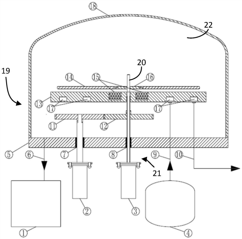
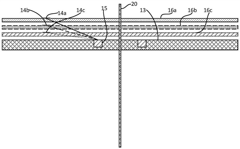
[0045] See attached figure 1 The Meissner effect test device provided in Embodiment 1 of the present invention includes a housing 19 , a base plate 13 , a lifting mechanism 21 , a permanent magnet 15 , a test piece tray 16 and a test piece 14 . An accommodating space 22 is formed inside the casing 19 , and the accommodating space 22 is used to provide a superconducting working environment for the test piece 14 . The lifting mechanism 21 includes a fixed end 3 and a lifting rod 20 , and the lifting rod 20 can be raised and lowered relative to the fixed end 3 . The permanent magnet 15 is fixedly arranged on the base plate 13, the test piece 14 is fixedly set on the test piece tray 16, the free end of the lifting rod 20 extends into the accommodating space 22, and the base plate 13 and the test piece tray 16 are respectively connected to the lifting rod 20, so that the distance between the specimen tray 14 and the base plate 13 can be adjusted.

[0046]In the application proces...

Embodiment 2

[0056] Different from the Meissner effect test device provided in the first embodiment of the present invention, in the Meissner effect test device provided in the second embodiment of the present invention, the substrate 13 is fixedly connected to the lifting rod 20, and the test piece tray 16 is opposite to the casing 19 At rest, the specimen tray 16 and the lifting rod 20 constitute a moving pair. The working principle of the second embodiment of the present invention is the same as that of the first embodiment of the present invention, except that the components that move up and down with the elevating rod 20 are replaced by the base plate 13, and other principles will not be repeated here.

Embodiment 3

[0058] Different from the Meissner effect test device provided in Embodiment 1 of the present invention, in the Meissner effect test device provided in Embodiment 3 of the present invention, the cooling medium channels 17 are arranged in concentric circles, and the distance between two adjacent concentric circles is connected. In this case, since the contact area between the cooling medium and the substrate 13 is larger, the cooling of the substrate 13 can be better achieved.


PUM


Abstract

The invention provides a Meissner effect test device. The Meissner effect test device comprises a shell (19), a base plate (13), a lifting mechanism (21), a permanent magnet (15), a test piece tray (16) and a to-be-tested piece (14), wherein an accommodating space (22) is formed in the shell (19) and used for providing a superconducting working environment for the to-be-tested piece (14); the lifting mechanism (21) comprises a fixed end (3) and a lifting rod (20), and the lifting rod (20) can ascend and descend relative to the fixed end (3); and the permanent magnet (15) is fixedly arranged onthe base plate (13), the to-be-tested piece (14) is fixedly arranged on the test piece tray (16), the free end of the lifting rod (20) extends into the accommodating space (22), and the base plate (13) and the test piece tray (16) are respectively connected to the lifting rod (20), so that the distance between the test piece tray (14) and the base plate (13) is adjustable. The device is easy to understand, simple in structure, convenient to operate and capable of accurately simulating a Meissner effect test.

Description

technical field [0001] The invention relates to the technical field of superconductivity, in particular to a Meissner effect test device. Background technique [0002] The Meissner effect is the repulsion of the magnetic field during the phase transition of a superconductor from a normal state to a superconducting state. It was measured by Walter Meissner and Robert Oxenfeld in superconducting tin and lead samples in 1933. They found that in the presence of a magnetic field, the samples were cooled below their superconducting phase transition temperature. Below the phase transition temperature, the sample cancels out almost all the magnetic fields inside. They detected this effect only indirectly; because the magnetic flux in superconductors is conserved, when the field inside decreases, the field outside increases. This experiment was the first to demonstrate that superconductors are more than perfect electrical conductors and provides a unique defining property for the s...

Claims


Application Information

Patent Timeline
Patent Type & Authority Applications(China)
IPC IPC(8): G01R33/035G01R1/04
CPCG01R1/0408G01R33/035
Inventor 洪军
Owner 北京瑞尔腾普装备科技有限公司
Features
  • R&D
  • Intellectual Property
  • Life Sciences
  • Materials
  • Tech Scout
  • Unparalleled Data Quality
  • Higher Quality Content
  • 60% Fewer Hallucinations
Learn More