Supercharge Your Innovation With Domain-Expert AI Agents!

Obstacle detection method and device, electronic equipment and storage medium

An obstacle detection and obstacle detection technology, which is applied in the field of devices, electronic equipment and storage media, and obstacle detection methods, can solve problems such as difficulty in obtaining the final control strategy and increasing the difficulty of decision-making by the decision-making module

Pending Publication Date: 2020-12-15
HANGZHOU HIKVISION DIGITAL TECH
View PDF15 Cites 5 Cited by
  • Summary
  • Abstract
  • Description
  • Claims
  • Application Information

AI Technical Summary

Problems solved by technology

[0005] Obviously, since the obstacle detection results corresponding to each sensor may have certain defects, it will increase the decision-making difficulty of the decision-making module to determine the final control strategy, making it difficult to obtain a better final control strategy

Method used


Image

  • Obstacle detection method and device, electronic equipment and storage medium
  • Obstacle detection method and device, electronic equipment and storage medium
  • Obstacle detection method and device, electronic equipment and storage medium

Examples


Embodiment 1

[0138] Embodiment 1, when the preset LSTM network has only one layer of LSTM network structure, use Figure 5 As an example, the method of training the preset LSTM network to obtain the calibration model is as follows:

[0139] x i (i∈[1,n]) and y i (i∈[1,n]) are the input and output data of the preset LSTM network, specifically, x i is the ultrasonic measurement value of the i-th sample, y i is the predicted value of the ultrasonic measurement value of the i-th sample, and y i The corresponding target truth value is x i+1 , that is, the ultrasonic measurement value of the i+1th sample. In addition, h i is the network hidden layer state of the preset LSTM network.

[0140] In the actual training process, the scheme of predicting the ultrasonic measurement value of the next sample by using the ultrasonic measurement value of the previous sample is adopted. Therefore, the preset LSTM network is a self-supervised network, and no additional training is required for the ultr...

Embodiment 2

[0141] Embodiment 2, when the preset LSTM network has a multi-layer LSTM network structure, with Figure 6 As an example, the method of training the preset LSTM network to obtain the calibration model is as follows:

[0142] For the first layer LSTM network structure, the preset sample ultrasonic measurement value x 1 -x n Input into the first layer LSTM network structure, get x 1 -x n The corresponding predicted value y 1 -y n , and determine the predicted value y 1 -y n the corresponding real value. Among them, the predicted value y 1 -y n The corresponding actual value is the preset sample ultrasonic measurement value x 2 -x n+1 . Furthermore, the loss value between each predicted value and the corresponding true value is calculated. In this way, the training of the first-layer LSTM network structure of the preset LSTM network can be completed.

[0143] For the second layer LSTM network structure, the predicted value y of the first layer 1 -y n-1 As input da...


PUM


Abstract

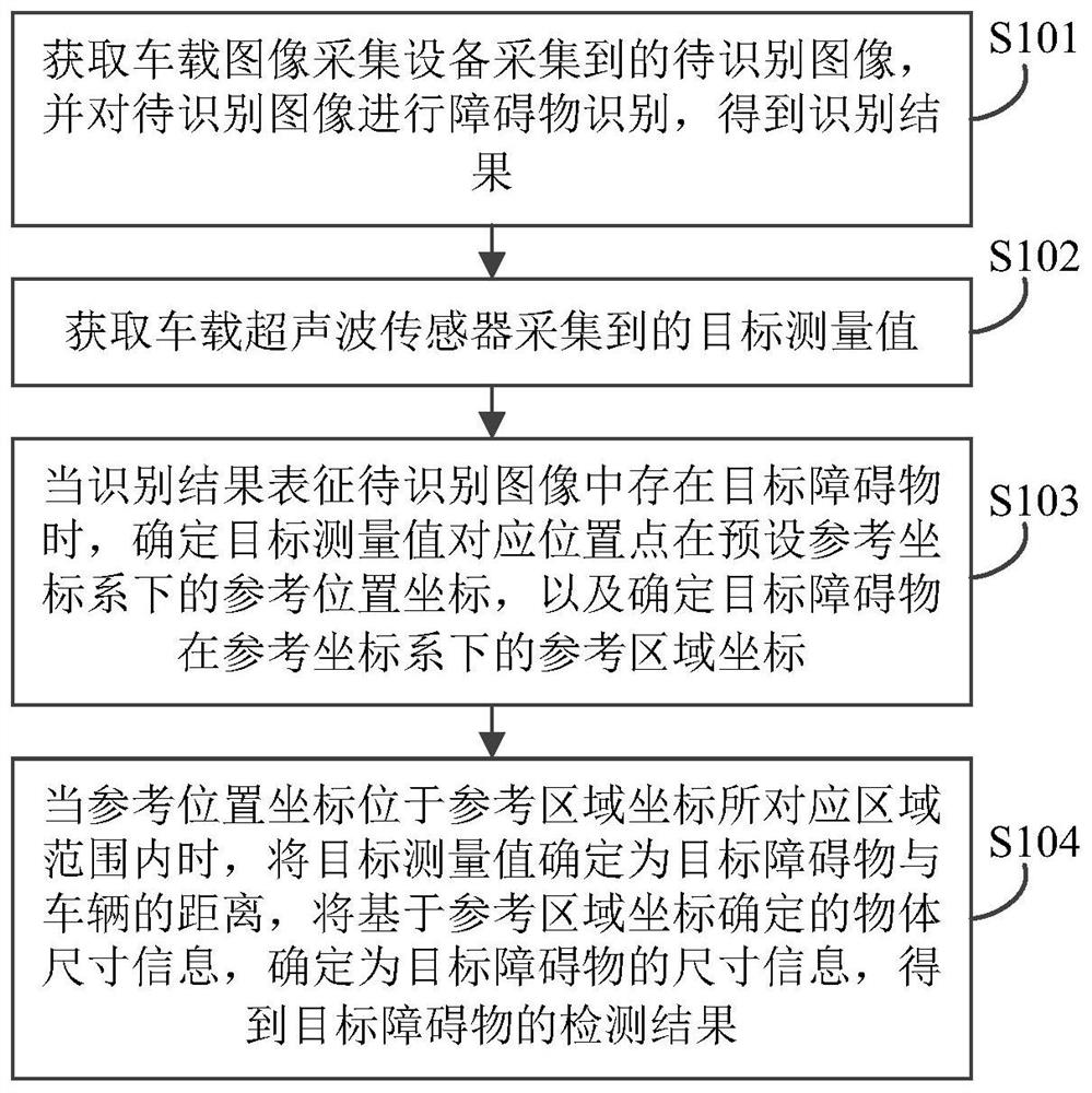
The embodiment of the invention provides an obstacle detection method and device, electronic equipment and a storage medium. The method is applied to a vehicle-mounted advanced driving assistance system and comprises the following steps: when an identification result of a to-be-identified image acquired by vehicle-mounted image acquisition equipment represents that a target obstacle exists in theto-be-identified image, determining a reference position coordinate of a position point corresponding to a target measurement value under a preset reference coordinate system, determining reference area coordinates of the target obstacle under a reference coordinate system; and when the reference position coordinates are located in the area range corresponding to the reference area coordinates, determining the target measurement value as the distance between the target obstacle and the vehicle, determining the object size information determined based on the reference area coordinates as the size information of the target obstacle, and obtaining the detection result of the target obstacle. Compared with the prior art, by applying the scheme provided by the embodiment of the invention, the decision-making difficulty of the decision-making module can be reduced, and an optimal final control strategy is obtained.

Description

technical field [0001] The present invention relates to the technical field of driving assistance, in particular to an obstacle detection method, device, electronic equipment and storage medium. Background technique [0002] In recent years, with the rapid development of autonomous driving technology, the environmental perception problem in the process of vehicle operation is particularly important. Among them, the obstacle detection problem is the most important part of the environmental perception problem. [0003] In related technologies in the field of ADAS (Advanced Driver Assistance Systems, advanced driver assistance systems), multi-sensors are used to detect obstacles. [0004] Specifically, multiple sensors are used to collect data respectively, and after the data collected by each sensor is obtained, obstacle analysis is performed on the data collected by each sensor, so as to determine the obstacle detection result corresponding to each sensor. Furthermore, the o...

Claims


Application Information

Patent Timeline
IPC IPC(8): G06K9/00G06K9/32
CPCG06V20/58G06V10/25
Inventor 安建平
Owner HANGZHOU HIKVISION DIGITAL TECH
Features
  • R&D
  • Intellectual Property
  • Life Sciences
  • Materials
  • Tech Scout
  • Unparalleled Data Quality
  • Higher Quality Content
  • 60% Fewer Hallucinations
Learn More