Method and system for determining roadway support area and support mode

A technology for roadway support and area, which is applied in earthwork drilling, data processing applications, instruments, etc., can solve the problem of not distinguishing between temporary support and permanent support, high roadway support and maintenance costs, and failure to consider support. The problem of project timeliness and other issues has achieved the effect of reducing support costs and maintenance costs, improving construction progress and construction quality, and reducing the difficulty of decision-making.

Active Publication Date: 2022-03-29
CENT SOUTH UNIV
View PDF7 Cites 0 Cited by
  • Summary
  • Abstract
  • Description
  • Claims
  • Application Information

AI Technical Summary

Problems solved by technology

The existing roadway support method adopts the traditional, shallow, global support based on RQD (rock quality index), that is, all areas of the entire roadway excavation face must be supported, and the cost of such a support method is It is very high, neither considering the timeliness of the support project, that is, not distinguishing between temporary support and permanent support, nor considering the dynamics of the deep, such as fault slippage, blasting, rockburst, etc., resulting in collapse after support, The phenomenon of supporting and collapsing makes the support and maintenance cost of the roadway remain high

Method used


Image

  • Method and system for determining roadway support area and support mode
  • Method and system for determining roadway support area and support mode
  • Method and system for determining roadway support area and support mode

Examples


Embodiment 1

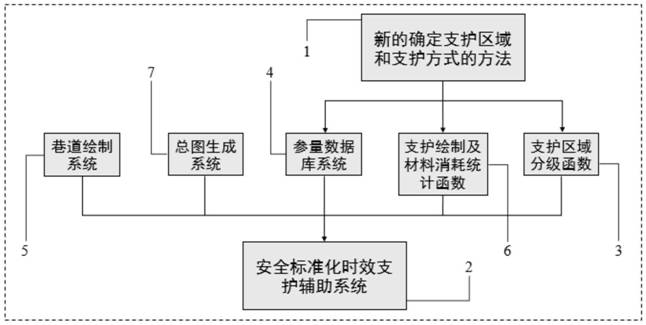
[0049] This embodiment provides a method for determining the roadway support area and support mode, such as figure 1 shown, including the following steps:

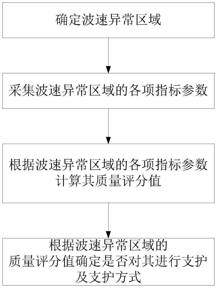
[0050] Step 1. Use the microseismic monitoring system installed underground to determine the abnormal wave velocity areas in the roadway excavation face, such as low-velocity areas and high-speed areas;

[0051] Step 2, carry out exploration, geophysical prospecting and test collection of various index parameters for each wave velocity anomaly area;

[0052] Step 3, according to the index parameters collected in step 2, calculate the quality score value G of each wave velocity abnormal region;

[0053] Step 4. Determine the support area and support method according to the quality score value G, that is, determine which areas with abnormal wave velocity need to be supported and determine the corresponding support method.

Embodiment 2

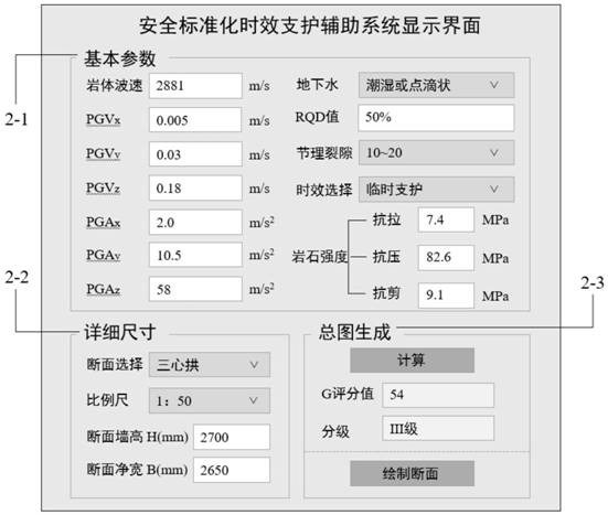
[0055] This embodiment is based on embodiment 1, and in said step 2, index parameters include RQD, rock mass wave velocity V 波 , peak seismic velocity PGV, peak seismic acceleration PGA, groundwater condition W (determined in combination with basic quality index BQ of rock mass), joint frequency J w and rock strength Q; where the seismic peak velocity PGV includes the seismic peak velocity PGV in the three directions of x, y, and z x 、PGV y and PGV z ;Earthquake peak acceleration PGA includes earthquake peak acceleration PGA in three directions of x, y, and z x 、PGA y and PGA z ;Therefore, a total of 11 indicator parameters are included.

[0056] The joint frequency J w Refers to the number of joints per meter distance (articles / m); the RQD, rock mass wave velocity V 波 , joint frequency J w and the value of rock strength Q can be determined based on existing technologies.

Embodiment 3

[0058] In this embodiment, on the basis of Embodiment 2, the peak seismic velocity PGV and peak seismic acceleration PGA are parameters related to the source mechanism (source type, vibration direction), which can invert the source type.

[0059] Its solution process is as follows:

[0060] First, the full waveform inversion method is used to invert the seismic moment tensor M(M xx ,M yy ,M zz ,M xy ,M xz ,M yz ), different source types (four sources of pure compression failure, pure shear failure, pure explosion failure, and pure tension failure) can be described by the combination of seismic moment tensors;

[0061] The displacement response is then calculated using Green's functions (GFs) to model the propagation of seismic waves between the source and sensor locations:

[0062] u n (s,t)=M pq *G np,q (s,t;ε,t 0 )n,p,q=x,y,z

[0063] u n (s, t) represents the displacement in the n direction at time t at the field point s recorded by the sensor, M pq Indicates t...


PUM


Abstract

The invention discloses a method and system for determining the roadway support area and support mode. The method includes the following steps: step 1, determining each abnormal wave speed area in the roadway excavation working face; step 2, collecting the data of each wave speed abnormal area Various index parameters; step 3, according to the index parameters collected in step 2, calculate the quality score value G of each abnormal wave velocity area; step 4, determine the support area and support method according to the quality score value G, that is, determine which wave velocity abnormal areas Need to support and determine the corresponding support method. The technical scheme provided by the invention can not only ensure the safety of roadway support, but also reduce the cost of roadway support.

Description

technical field [0001] The invention relates to the field of mine underground safety, in particular to a method and a system for determining a roadway support area and a support mode. Background technique [0002] With the extension of the mine to the deep and the unconventional development of the mine in recent years, the construction quality problems in the roadway excavation are prominent, and the construction cost remains high. The amount of maintenance work is large, there are many hidden dangers in construction safety, and the cost of roadway maintenance is high. [0003] The roadway support of mining engineering is a key construction technology to reduce the damage of the shaft and roadway and prevent the occurrence of roof caving accidents. The roadway support is divided into temporary support and permanent support. The existing roadway support method adopts the traditional, shallow, global support based on RQD (Rock Quality Index), that is, all areas of the entire ...

Claims


Application Information

Patent Timeline
Patent Type & Authority Patents(China)
IPC IPC(8): E21F17/18E21F17/00G06Q50/02
CPCE21F17/18E21F17/00G06Q50/02
Inventor 董陇军王剑孙道元
Owner CENT SOUTH UNIV
Why Eureka
Try Eureka