Supercharge Your Innovation With Domain-Expert AI Agents!

A data center busbar elastic connector

A data center and plug-in device technology, applied in the direction of clamping/spring connection, connection, conductive connection, etc., can solve problems such as poor contact between plug-in terminals and busbars, power distribution failure of data neutral busbar, and limited service life of ordinary springs , to achieve the effect of compact and stable structure, increase in current carrying capacity, and avoid power failure problems.

Active Publication Date: 2022-07-05
ZHENJIANG GARDERMOEN INTELLIGENT POWER TECH CO LTD
View PDF0 Cites 0 Cited by
  • Summary
  • Abstract
  • Description
  • Claims
  • Application Information

AI Technical Summary

Problems solved by technology

[0003] In the prior art, the data center line bus connection device includes a plug housing, a phase line pin or a PE pin located in the plug housing, etc., and a coil spring is arranged between the phase line pin and the plug housing, and when the pin is connected to the bus The row contact squeezes and compresses the spring, so that the spring restoring force presses the pins into contact with the busbar. Due to the small contact area between the pins and the busbar in the existing structure, there are problems of small carrying capacity and high heat generation. At the same time After a long period of time, the coil spring can hardly bear the high temperature transmitted by the pins and burns out. Moreover, the life of the ordinary spring is limited, and it will lose its elasticity after a long time, resulting in poor contact between the plug terminal and the busbar, causing power outage, and causing the power distribution failure of the data neutral busbar

Method used


Image

  • A data center busbar elastic connector
  • A data center busbar elastic connector
  • A data center busbar elastic connector

Examples


Embodiment Construction

[0029] The specific embodiments of the present invention will be further described below with reference to the accompanying drawings.

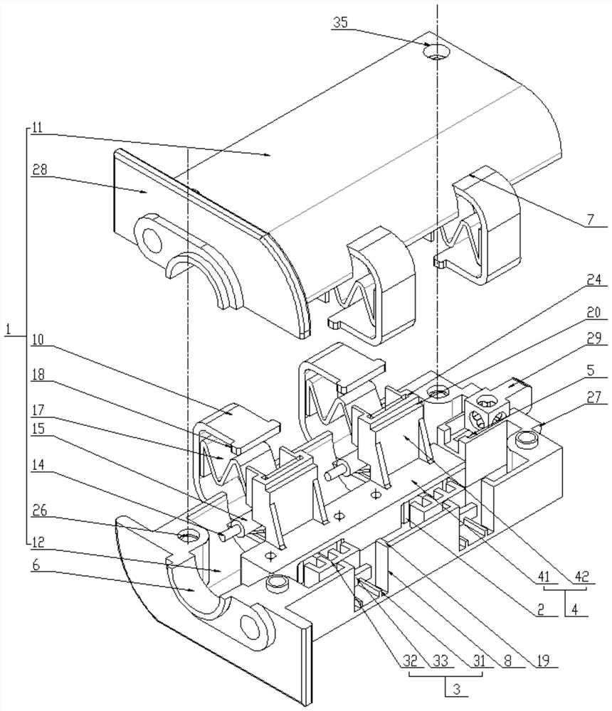
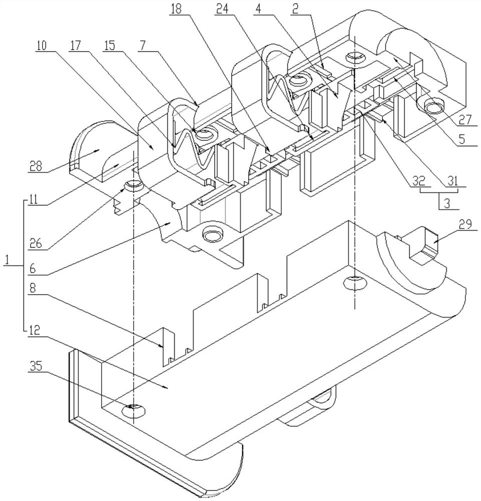
[0030] A data center busbar elastic plug-in device, comprising a plug-in casing 1, the two ends of the plug-in casing 1 are respectively provided with a PE terminal slot 5 and a wiring hole 6, wherein the plug-in casing 1 includes a structure The upper casing 11 and the lower casing 12 are consistent and oppositely connected. The upper casing 11 and the lower casing 12 are provided with a first notch 7 or a second notch corresponding to the first notch 7 on the same side. 8, a guide frame 2 is provided on one side of the first notch 7, and a limit post 9 is arranged in the guide frame 2. The notch 8 and the contact copper sheet 10 in a C-shaped structure that slides linearly along the guide frame 2;

[0031] The guide frame 2 includes two guide plates 21 connected to the side wall and bottom of the upper casing 11 or the lower casing 12 and l...


PUM


Abstract

The invention relates to an elastic connecting device for a bus bar of a data center, which comprises a connecting casing, a PE terminal slot and a wiring hole are arranged on the connecting casing, and the connecting casing comprises an upper casing which has the same structure and is connected with each other in opposite ways. and the lower casing, the upper casing and the lower casing are provided with a first notch or a second notch on the same side, and the limiting column of the guide frame on one side of the first notch is provided with a C-shaped sliding along the guide frame. The contact copper sheet of the structure, the contact copper sheet is connected with a wire, the upper casing and the lower casing are respectively provided with fixed and oppositely matched and limited shrapnel mounting brackets, and the ends of the shrapnel mounting brackets are arranged against the inner wall of the contact copper sheet. The shrapnel has a compact overall structure, easy installation, stable support and structure. When the shrapnel is rotated 90° to complete the insertion, the elastic deformation of the shrapnel completes the extruded contact with the busbar to obtain electricity, ensuring stable and reliable contact, increasing current carrying, reducing heat generation, and avoiding springs. Poor contact leads to power failure, which improves the safety, stability and transmission performance of the data center bus system.

Description

technical field [0001] The invention relates to a data center busbar elastic connecting device, belonging to the technical field of data center busbar power distribution. Background technique [0002] Data center busbars are widely used between transformers, power distribution cabinets, etc., as well as in the distribution center load tree trunk wiring power supply system. At the same time, it is equipped with units such as incoming boxes and plug-in devices, which are used for main line power transmission and distribution. After laying, data can be Insert the patching device at any position on the shell side of the central busbar opening, and use the conductive phase wire pin structure of the patching device to contact the busbar copper bar for conduction, and then connect with the distribution unit to realize the connection and transmission of the distribution, distribution, distribution, and transmission of electricity. [0003] The prior art data neutral busbar connectio...

Claims


Application Information

Patent Timeline
Patent Type & Authority Patents(China)
IPC IPC(8): H01R9/16H01R9/24H01R4/48
CPCH01R9/16H01R9/24H01R9/2416H01R4/4809
Inventor 马见雄李广卿胡桥宇朱恩元方加明
Owner ZHENJIANG GARDERMOEN INTELLIGENT POWER TECH CO LTD
Features
  • R&D
  • Intellectual Property
  • Life Sciences
  • Materials
  • Tech Scout
  • Unparalleled Data Quality
  • Higher Quality Content
  • 60% Fewer Hallucinations
Learn More