Component carrier structure aligned by combining evaluation pad pattern and hole pattern alignment marks

A technology for component bearing and alignment marks, which is used in electrical components, multilayer circuit manufacturing, printed circuit manufacturing, etc., to achieve high-precision and high-capacity effects

Active Publication Date: 2020-12-15
AT&S (CHONGQING) CO LTD
View PDF21 Cites 1 Cited by
  • Summary
  • Abstract
  • Description
  • Claims
  • Application Information

AI Technical Summary

Problems solved by technology

[0003] Also, proper alignment of the components of the part carrier is an issue during the manufacturing process

Method used


Image

  • Component carrier structure aligned by combining evaluation pad pattern and hole pattern alignment marks
  • Component carrier structure aligned by combining evaluation pad pattern and hole pattern alignment marks
  • Component carrier structure aligned by combining evaluation pad pattern and hole pattern alignment marks

Examples


Embodiment Construction

[0066] Exemplary embodiments will be described in further detail, and some basic considerations will be summarized based on exemplary embodiments of the present invention that have been developed, before referring to the drawings.

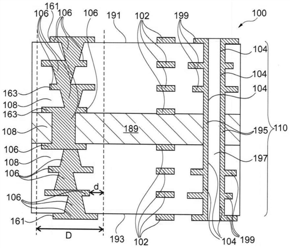
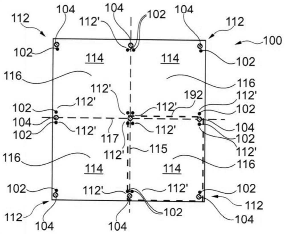
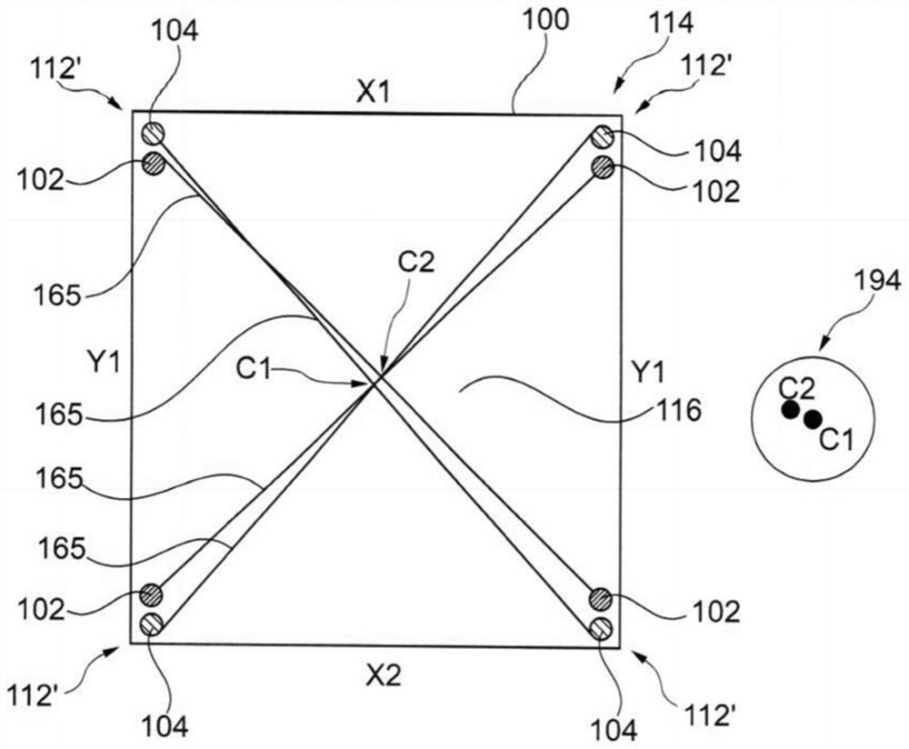
[0067] According to an exemplary embodiment of the present invention, the determination of alignment information based on pad-type alignment marks is synergistically combined with the determination of alignment information based on one or more hole-type alignment marks.

[0068] In a particularly preferred embodiment, it has been found that pad alignment alone is more accurate than hole alignment. Therefore, according to an exemplary embodiment of the present invention, preliminary alignment information may be derived using pad alignment alone, ie hole type alignment marks are not considered in this first stage. Subsequently, the alignment information may be made more accurate, more precise or may be improved by additionally taking into account the...


PUM


Abstract

The invention relates to a method of aligning a component carrier structure (100). The method comprises of forming one or more pad-type alignment marks (102) on and / or in the component carrier structure (100); forming one or more pass alignment marks (104) on the component carrier structure (100) and / or in the component carrier structure (100); and determining alignment information for aligning the component carrier structure (100) by combining alignment information derived based on the one or more pad-type alignment marks (102) and the one or more pass-type alignment marks (104). The invention also relates to a component carrier structure, a device for aligning the component carrier structure, a computer-readable medium, a program unit and a batch group consisting of component carriers.

Description

technical field [0001] The invention relates to a method for aligning component carrier structures, a component carrier structure, a device for aligning component carrier structures, a computer-readable medium, a program unit and a batch of component carriers . Background technique [0002] Against the backdrop of increasing product functions of component carriers equipped with one or more electronic components, increasing miniaturization of these electronic components, and increasing number of electronic components to be mounted on component carriers such as printed circuit boards More and more powerful array-like components or packages with several electronic components with multiple contacts or connections with smaller spacing between these contacts are used. Removing the heat generated by these electronic components and the component carrier itself during operation has become an increasing problem. At the same time, the component carrier should be mechanically robust a...

Claims


Application Information

Patent Timeline
Patent Type & Authority Applications(China)
IPC IPC(8): H05K3/46
CPCH05K3/4638
Inventor 吴昱辉
Owner AT&S (CHONGQING) CO LTD
Why Eureka
Try Eureka