
Multi-degree-of-freedom variable-rigidity joint mechanical arm

A technology of variable stiffness and manipulators, applied in manipulators, program-controlled manipulators, claw arms, etc., can solve problems such as poor safety, and achieve the effects of improving bearing capacity, fast response to stiffness adjustment, and low energy consumption for stiffness adjustment

Active Publication Date: 2020-12-18
HARBIN INST OF TECH
View PDF6 Cites 3 Cited by
  • Summary
  • Abstract
  • Description
  • Claims
  • Application Information

AI Technical Summary

Problems solved by technology

[0002] Traditional industrial robots are designed with rigid joint manipulators, which have high position control accuracy, but poor safety, and generally work in a closed environment
Robot systems such as service robots and field special operation robots generally work in an open environment, not only need to deal with flexible and complex operation tasks, but also have requirements for human-computer safety interaction, robot and unstructured environment interaction, therefore, the traditional Rigid articulated manipulators cannot well meet the operational needs of collaborative robots

Method used


Image

  • Multi-degree-of-freedom variable-rigidity joint mechanical arm
  • Multi-degree-of-freedom variable-rigidity joint mechanical arm
  • Multi-degree-of-freedom variable-rigidity joint mechanical arm

Examples


Embodiment Construction

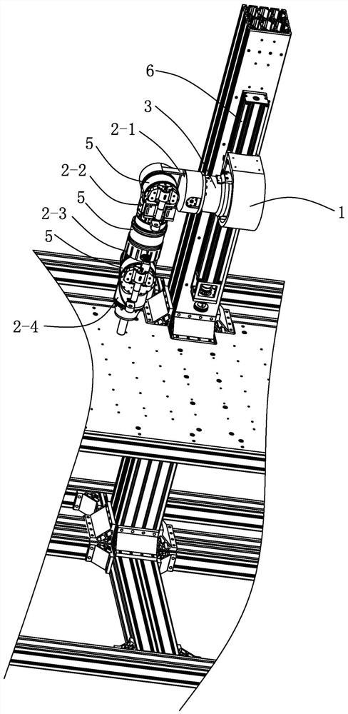
[0036]SeeFigure 1-Figure 4 ,Figure 13 withFigure 14 As shown, a multi-degree-of-freedom variable-rigidity joint mechanical arm of this embodiment includes a mounting seat 1, a base joint 3, three end joints 5, and four connecting rods;

[0037]The mounting base 1 is installed on the existing linear sliding table 6, the input end of the base joint 3 is connected to the mounting base 1, and the output end of the base joint 3 is connected to the first link 2-1, the first link 2-1 Connected to the input end of the first end joint 5, the output end of the first end joint 5 is connected to the second link 2-2, and the second link 2-2 is connected to the input end of the third end joint 5, The output end of the third end joint 5 is connected to the third link 2-3, the third link 2-3 is connected to the input end of the fourth end joint 5, and the output end of the fourth end joint 5 is connected to the fourth link. Connecting rod 2-4 connection;

[0038]The four links are the first link 2-1, th...


PUM


Abstract

The invention discloses a multi-degree-of-freedom variable-rigidity joint mechanical arm. The multi-degree-of-freedom variable-rigidity joint mechanical arm comprises a mounting base, a base joint, three tail end joints and four connecting rods; an input end of the base joint is connected with the mounting base, and an output end of the base joint is connected with the first connecting rod; the first connecting rod is connected with an input end of the first tail end joint; an output end of the first tail end joint is connected with the second connecting rod; the third connecting rod is connected with an input end of the fourth tail end joint; an output end of the fourth tail end joint is connected with the fourth connecting rod; the base joint comprises a first joint shell, a main drivingmodule, an elastic module and a rigidity adjusting module; the first joint shell is connected with the first connecting rod; each tail end joint comprises a second joint shell, a main driving mechanism, an elastic mechanism and a rigidity adjusting mechanism; and the second connecting rod, the third connecting rod and the fourth connecting rod are separately connected with the second joint shellsof the corresponding tail end joints. The mechanical arm is wide in rigidity adjusting range, and can meet the safety interaction demands of cooperative mechanical arms.

Description

Technical field[0001]The invention relates to a mechanical arm, in particular to a multi-degree-of-freedom variable stiffness joint mechanical arm. It belongs to the field of robot joint technology.Background technique[0002]Traditional industrial robots are designed with rigid joint manipulators, which have high position control accuracy, but their safety is poor, and they generally work in a closed environment. However, robot systems such as service robots and field special operation robots generally work in an open environment. They not only need to deal with flexible and complex operation tasks, but also have requirements for safe human-machine interaction, and interaction between robots and unstructured environments. Therefore, the traditional Rigid joint manipulators cannot well meet the operational requirements of collaborative robots.Summary of the invention[0003]In order to overcome the shortcomings of the prior art, the present invention provides a multi-degree-of-freedom v...

Claims


Application Information

Patent Timeline
Patent Type & Authority Applications(China)
IPC IPC(8): B25J18/00B25J9/10B25J17/02
CPCB25J9/1045B25J17/0266B25J18/00
Inventor 金弘哲刘章兴赵杰黄卫金王彬峦
Owner HARBIN INST OF TECH
Learn More