
Compact modular variable rigidity joint

A variable stiffness, modular technology, applied in manipulators, manufacturing tools, joints, etc., can solve the problems that rigid joints cannot well meet the operational requirements of collaborative robots, cannot achieve joint load decoupling, and joint stiffness linearity is poor. , to achieve the effect of compact design, good linearity, and elimination of additional bending moments

Active Publication Date: 2020-12-18
HARBIN INST OF TECH
View PDF6 Cites 8 Cited by
  • Summary
  • Abstract
  • Description
  • Claims
  • Application Information

AI Technical Summary

Problems solved by technology

[0002] Traditional industrial robots adopt rigid joint design, which has high position control accuracy, but poor safety, and generally work in a closed environment
Robot systems such as service robots and field special operation robots generally work in an open environment, not only need to deal with flexible and complex operation tasks, but also have the requirements for human-computer safety interaction and interaction between robots and unstructured environments. Therefore, the traditional Rigid joints cannot well meet the operational needs of collaborative robots
[0003] In the prior art, screw nuts are used to adjust the joint stiffness (such as the publication number CN 111390695A, a general-purpose variable stiffness joint mechanical arm joint), which has the disadvantages of large friction and high energy consumption of the stiffness adjustment system; in addition, this arc-based The variable stiffness structure of the shape surface has a strong nonlinear stiffness curve, and it is impossible to achieve a wide range of stiffness adjustment near the equilibrium position
Its stiffness value will increase rapidly with the increase of joint load, and the decoupling of joint load and stiffness value cannot be realized. Therefore, the stiffness characteristics are easily affected by joint load
There is also the use of torsion springs to adjust the stiffness. This method will have the defects of poor linearity of joint stiffness, high hysteresis and poor stability.

Method used


Image

  • Compact modular variable rigidity joint
  • Compact modular variable rigidity joint
  • Compact modular variable rigidity joint

Examples


Embodiment Construction

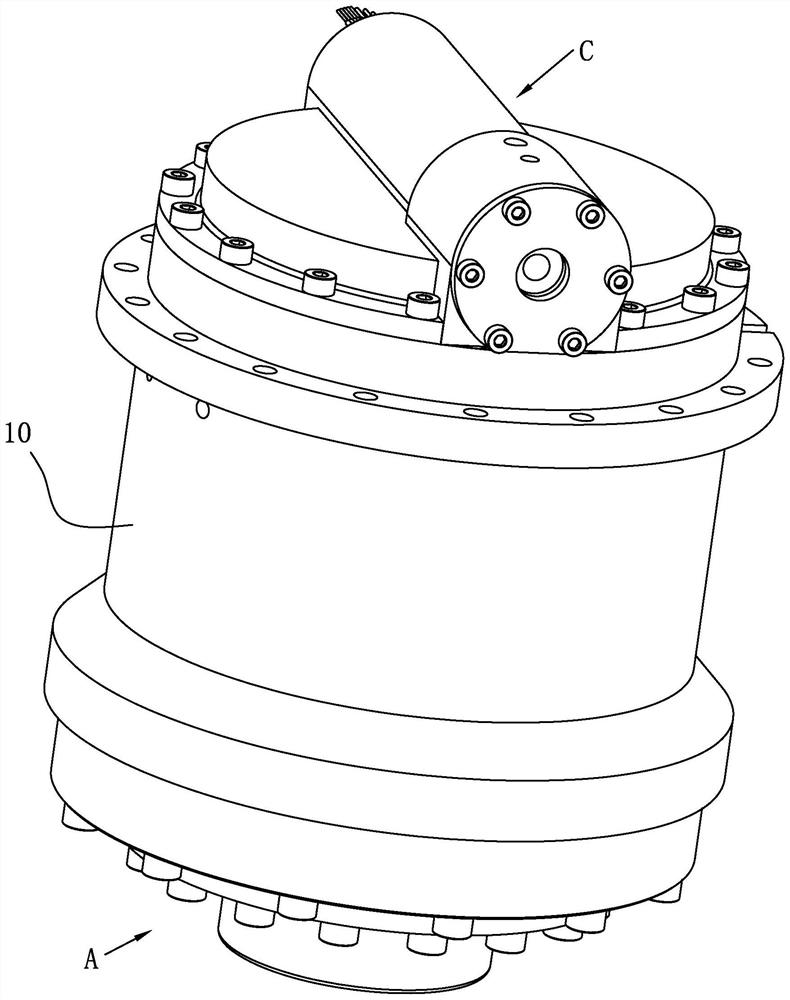
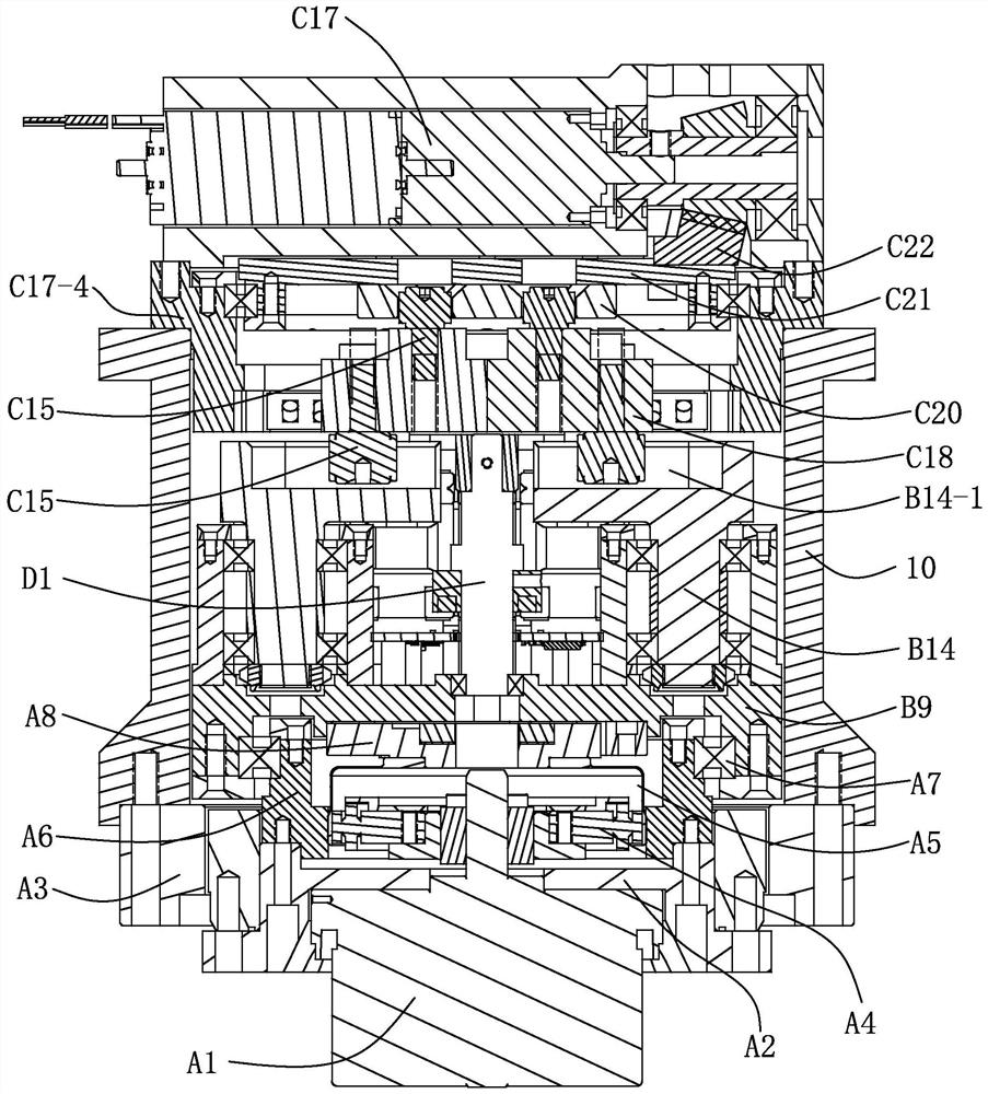
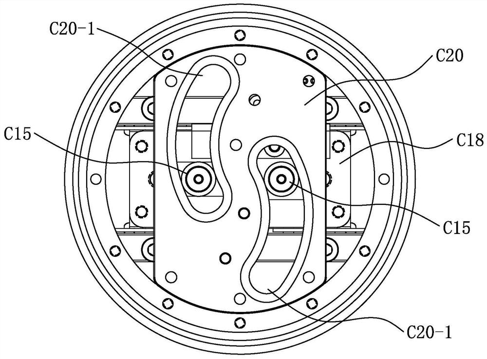
[0027] see Figure 1-Figure 6 As shown, a compact modular variable stiffness joint of this embodiment includes a joint housing 10, a main drive module A, an elastic module and a stiffness adjustment module C;

[0028] The elastic module includes a variable stiffness base B9, a linear spring module B13 and a lever assembly B14;

[0029] The main drive module A is arranged in the joint housing 10 and the two can rotate relatively, the elastic module is arranged in the joint housing 10, and the variable stiffness base B9 is driven to rotate by the output end of the main drive module A; the variable stiffness base B9 is rotatably provided with two axisymmetrically arranged lever assemblies B14, each lever assembly B14 has a sliding slot B14-1, one end of the sliding slot B14-1 is open, the other end is closed, and the two openings are oppositely arranged , the two outer walls of each chute B14-1 are respectively supported by a linear spring module B13, and the linear spring modul...


PUM


Abstract

The invention relates to a compact modular variable rigidity joint which comprises a joint housing, a main driving module, an elastic module and a rigidity adjusting module. The elastic module comprises a variable rigidity pedestal, a linear spring module and two lever assemblies; the rigidity adjusting module is driven by an output end of the main driving module to rotate; the two lever assemblies that are arranged in axial symmetry are rotatably arranged on the variable rigidity pedestal, each lever assembly is provided with a chute, and the linear spring module is slidably arranged on the variable rigidity pedestal; the rigidity adjusting module comprises a rigidity adjusting driver, a bevel gear pair, a cam disc base, a cam disc, a slide block and a first cam bearing follower; the rigidity adjusting driver is mounted on the joint housing, the cam disc base is rotatably arranged in the joint housing, two slide blocks are slidably arranged in the joint housing, and the first cam bearing followers are mounted on the opposite two side surface of each slide block, separately. The compact modular variable rigidity joint is large in rigidity adjusting range and large in bearing capacity and can meet flexible adjustment of the joint rigidity under different load circumstances.

Description

technical field [0001] The invention relates to a variable stiffness joint, in particular to a compact modular variable stiffness joint. The invention belongs to the technical field of robot joints. Background technique [0002] Traditional industrial robots are designed with rigid joints and have high position control accuracy, but their safety is poor, and they generally work in a closed environment. Robot systems such as service robots and field special operation robots generally work in an open environment, not only need to deal with flexible and complex operation tasks, but also have the requirements for human-computer safety interaction and interaction between robots and unstructured environments. Therefore, the traditional Rigid joints cannot well meet the manipulation requirements of collaborative robots. [0003] In the prior art, screw nuts are used to adjust the joint stiffness (such as the publication number CN 111390695A, a general-purpose variable stiffness j...

Claims


Application Information

Patent Timeline
Patent Type & Authority Applications(China)
IPC IPC(8): B25J17/00
CPCB25J17/00
Inventor 金弘哲刘章兴赵杰黄卫金王彬峦
Owner HARBIN INST OF TECH
Learn More