Product taking-out mechanism for battery box forming equipment

A molding equipment and product removal technology, applied in the direction of battery pack parts, circuits, electrical components, etc., can solve the problems of battery box collision, rupture, etc., and achieve the effect of increasing adsorption capacity, easy adsorption, and avoiding tilting

Pending Publication Date: 2020-12-18
重庆市海龙模具有限公司
View PDF0 Cites 2 Cited by
  • Summary
  • Abstract
  • Description
  • Claims
  • Application Information

AI Technical Summary

Problems solved by technology

However, in the process of turning, the battery box is easy to tilt under the action of inertia, and because the stroke of the mechanical arm is basically the same, when discharging, when the battery box is tilted, one side of the battery box will touch the ground first, and the other side of the battery box will come later. Landing on the ground, and the rear landing side is a certain distance away from the ground, the battery box is easy to collide with the ground and break

Method used


Image

  • Product taking-out mechanism for battery box forming equipment
  • Product taking-out mechanism for battery box forming equipment
  • Product taking-out mechanism for battery box forming equipment

Examples


Embodiment 1

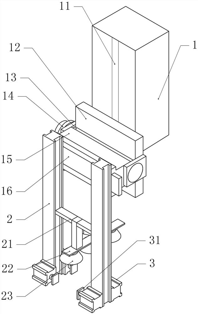
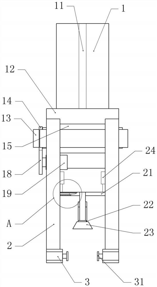
[0036] Basic as attached figure 1 And attached figure 2 Shown: a product take-out mechanism for battery box forming equipment, including a frame and a first linear module fixed on the frame with bolts, and a vertical bracket is bolted on the output end of the first linear module 1. A second vertical linear module 11 is fixed on the bracket 1 by bolts, and a fixed seat 12 is fixed by bolts on the output end of the second linear module 11. A steering mechanism is arranged on the fixed seat 12, and a clip is installed on the steering mechanism. holding mechanism and adsorption mechanism. When the first linear motor module is working, the support 1 is moved to the injection molding machine. When the second linear motor module is working, the position of the fixing seat 12 can be adjusted vertically, and then the height of the steering mechanism and the adsorption mechanism can be adjusted.

[0037] In this embodiment, the steering mechanism includes a rotating shaft 13 and a mo...

Embodiment 2

[0045] The difference between embodiment two and embodiment one is that, as attached Image 6 , attached Figure 7 And attached Figure 8 As shown, the negative pressure pump 4 is fixed with bolts on the bracket 1 , the air inlet of the negative pressure pump 4 is communicated with an air intake pipe 41 , the air intake pipe 41 is communicated with the sucker 23 , and the air outlet of the negative pressure pump 4 is communicated with an air outlet pipe 42 .

[0046] A cavity 34 is opened in the main clamping plate 31, and a secondary clamping plate 32 is horizontally slidably connected to both sides of the cavity 34. A return spring 36 is arranged between the two secondary clamping plates 32, and the cavity 34 passes through the outlet. The gas pipe 42 communicates with the negative pressure pump 4 , and the cavity 34 communicates with a pressure relief valve 35 . combined with Figure 8 As shown, several protrusions 33 are vertically slidably connected to the auxiliary cl...


PUM


Abstract

The invention relates to the technical field of battery box taking-out equipment, and discloses a product taking-out mechanism for battery box forming equipment. The product taking-out mechanism comprises a rack, wherein a first linear module is installed on the rack, a vertical support is installed at the output end of the first linear module, a second linear module is installed on the support, asteering mechanism is installed at the output end of the second linear module, and a clamping mechanism and an adsorption mechanism used for adsorbing a battery box are installed on the steering mechanism; the steering mechanism comprises an installation base and a rotating shaft rotationally connected with the support, the installation base is fixed to the rotating shaft, a driven gear is coaxially fixed to the rotating shaft, a driving part is arranged on the support, a driving gear engaged with the driven gear is coaxially fixed to an output shaft of the driving part, and a third linear module is fixed to the installation base; and the clamping mechanism comprises at least two sets of clamping assemblies fixed to the output end of the third linear module. The product taking-out mechanism is simple in structure, the battery box can be rapidly clamped, and the battery box is prevented from inclining.

Description

technical field [0001] The invention relates to the technical field of battery box taking out equipment, and specifically discloses a product taking out mechanism for battery box forming equipment. Background technique [0002] The battery box of the storage battery is used to hold the electrolyte and the plate group. The battery box should be acid-resistant, heat-resistant, and shock-resistant. In the past, it was mostly made of hard rubber. Now China has started to produce polypropylene plastic battery boxes. This kind of shell is not only acid-resistant, heat-resistant, and shock-resistant, but also has high strength. Light, beautiful appearance, transparent. [0003] The battery box is formed by injection molding, and the molded battery box is generally taken out manually, but this method is inefficient and has the risk of burns, and has been phased out. Now the most used way is to take the battery box through the robotic arm. The action of the robotic arm is: alignmen...

Claims


Application Information

Patent Timeline
Patent Type & Authority Applications(China)
IPC IPC(8): B29C45/42H01M2/02
CPCB29C45/4225
Inventor 颜美聪
Owner 重庆市海龙模具有限公司
Why Eureka
Try Eureka