Traffic road and bridge construction material mixing treatment device

A technology of material mixing, traffic road and bridge, applied in the direction of roads, roads, road repairs, etc., can solve the problems that affect the efficiency of construction, consume a lot of manpower and time, and achieve the effect of avoiding mutual interference, good effect, and improving the mixing effect

Inactive Publication Date: 2020-12-18
谢晓红
View PDF0 Cites 0 Cited by
  • Summary
  • Abstract
  • Description
  • Claims
  • Application Information

AI Technical Summary

Problems solved by technology

[0003] If the concrete is mixed at the construction site, it needs to consume a lot of manpower and time, which affects the efficiency of construction

Method used


Image

  • Traffic road and bridge construction material mixing treatment device
  • Traffic road and bridge construction material mixing treatment device
  • Traffic road and bridge construction material mixing treatment device

Examples


Embodiment 1

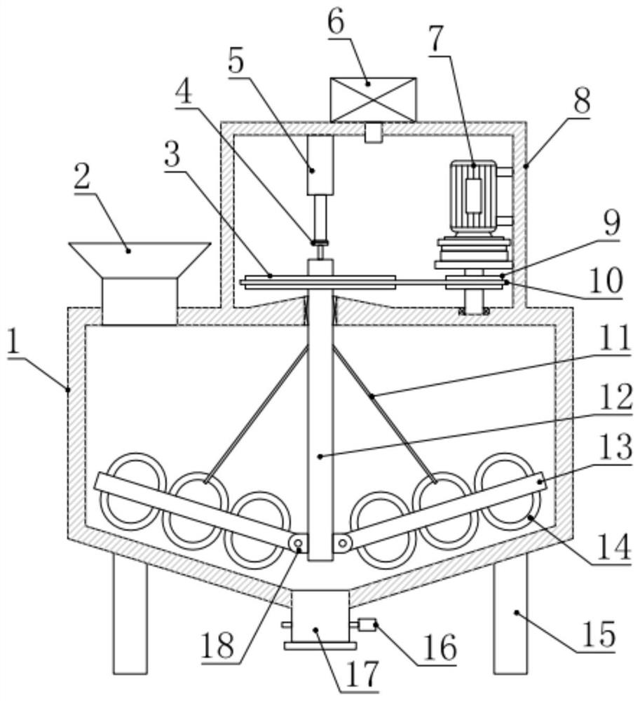
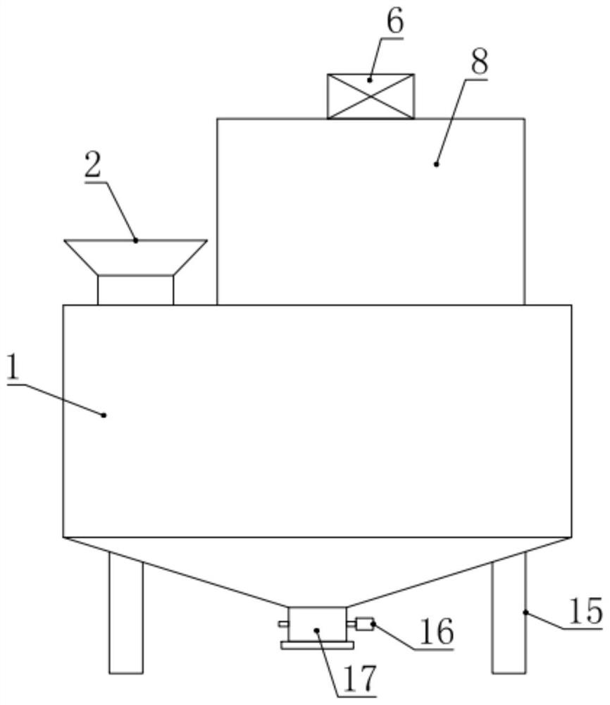
[0026] see Figure 1-2 , in an embodiment of the present invention, a device for mixing and processing traffic, road and bridge construction materials includes a mixing box 1 and a driving box 8, the driving box 8 is installed and fixed on the top of the mixing box 1, and a center is installed in the middle of the mixing box 1 Rotary tube 12, the central rotary tube 12 is connected with the top of the mixing box 1 in a sealed rotation, the upper end of the central rotary tube 12 is located in the drive box 8, and a cavity 22 is provided in the central rotary tube 12, and the inner cavity of the drive box 8 passes through the cavity. The cavity 22 communicates with the inner cavity of the mixing box 1, and the central transfer tube 12 is driven to rotate by the driving mechanism arranged in the driving box 8, and the driving mechanism includes a driven pulley 3, a driving motor 7, a driving pulley 9 and a transmission belt 10 , the driven pulley 3 is installed and fixed on the ...

Embodiment 2

[0029] see figure 1 , 3 And 4, the difference between this embodiment and embodiment 1 is:

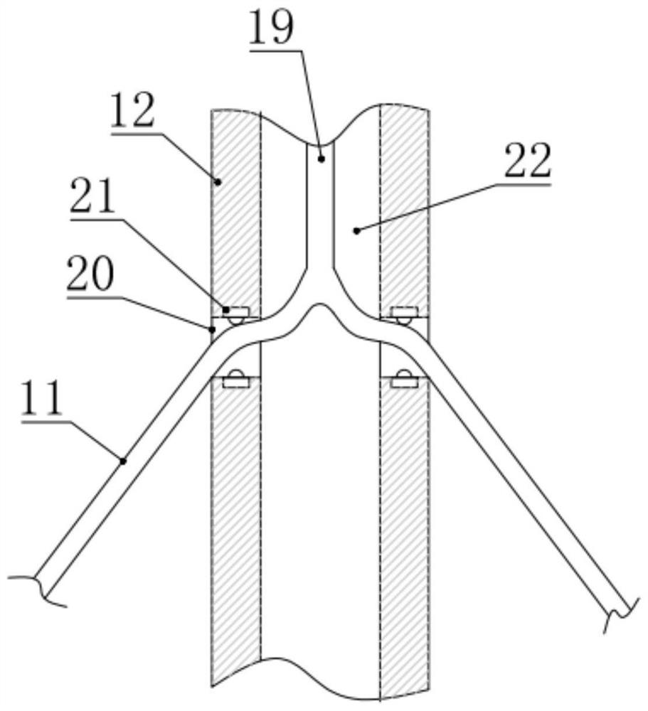
[0030] In this embodiment, the stirring mechanism 23 includes a stirring rod 13, a stirring ring 14 and a hinge support 18, the hinge support 18 is fixed on the lower end of the central rotating tube 12, and the hinge support 18 is hinged with a stirring rod 13 , the upper and lower sides of the stirring rod 13 are respectively installed and fixed with a plurality of semicircular stirring rings 14, and the cooperation of the stirring rod 13 and the stirring ring 14 has a good mixing effect on the material; one of the upper sides of the stirring rod 13 A steel wire rope 11 is connected to the stirring ring 14, and the other end of the steel wire rope 11 is connected to the lower end of the main steel wire rope 19 provided in the cavity 22. 4. It is used to prevent the main steel wire rope 19 and the support steel wire rope 11 from twisting the telescopic cylinder 5 when they rotate. ...


PUM


Abstract

The invention relates to the field of traffic road and bridge construction, in particular to a traffic road and bridge construction material mixing treatment device. The traffic road and bridge construction material mixing treatment device comprises a mixing box and a driving box, the driving box is installed and fixed to the top of the mixing box, a center rotating pipe is installed in the middleof the mixing box and driven by a driving mechanism arranged in the driving box to rotate, a plurality of stirring mechanisms are circumferentially distributed and installed at the lower end of the center rotating pipe, and the outer ends of the stirring mechanisms are driven by a telescopic cylinder arranged on the inner side of the driving box to swing upwards; and an air pump used for blowingair into an inner cavity of the driving box is further installed at the top of the driving box. According to the traffic road and bridge construction material mixing treatment device, the stirring structure is novel, the angle can be dynamically adjusted, the pneumatic material turning function is achieved, and application and popularization are facilitated.

Description

technical field [0001] The invention relates to the field of traffic road and bridge construction, in particular to a device for mixing and processing traffic road and bridge construction materials. Background technique [0002] In the construction of roads and bridges, concrete is needed in many places. If the mixed concrete is transported to the construction site for laying, the concrete already has a certain degree of coagulation, and the strength of the concrete will decrease, and the quality of the road and bridge will also decrease. At the same time, it also reduces the service life of the road bridge. [0003] If the concrete is mixed at the construction site, it needs to consume a lot of manpower and time, which affects the efficiency of construction. Therefore, it is necessary to provide corresponding auxiliary devices for the staff to help the staff mix the materials and carry out road and bridge construction operations more conveniently. [0004] Therefore, in v...

Claims


Application Information

Patent Timeline
Patent Type & Authority Applications(China)
IPC IPC(8): E01C19/10
CPCE01C19/10E01C19/104
Inventor 谢晓红
Owner 谢晓红
Why Eureka
Try Eureka