A wear warning control method for an automatic transmission shift system

A technology of automatic transmission and control method, applied in the field of transmission system, can solve the problems of wear and tear of the shifting system, inability to effectively identify the amount of wear, frequent occurrence, etc., and achieve the effect of reducing the frequency of occurrence

CN112096832BActive Publication Date: 2022-06-03湖南长峰重工科技有限公司
7 Cites 0 Cited by

Patent Information

Authority / Receiving Office
CN · China
Patent Type
Patents(China)
Current Assignee / Owner
Publication Date
2022-06-03

Smart Images

  • Figure 1
    Figure 1
  • Figure 2
    Figure 2
  • Figure 3
    Figure 3
Patent Text Reader

Abstract

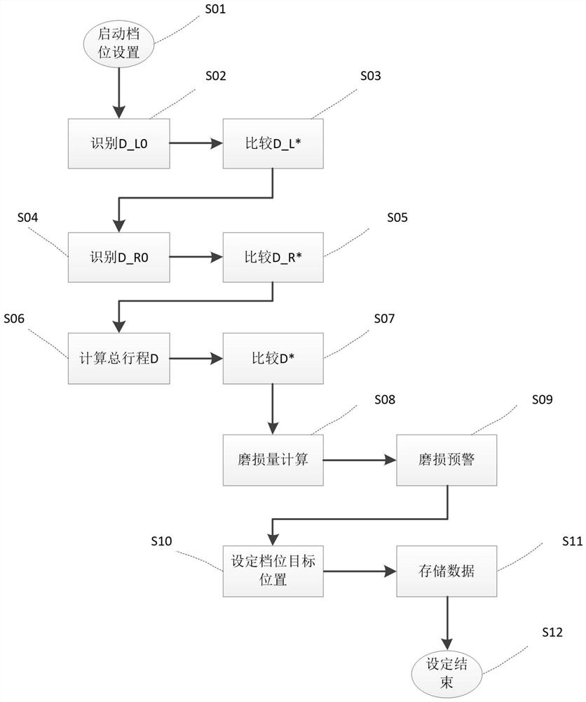
The invention discloses an early warning control method for wear and tear of an automatic transmission shift system, which is applied to a transmission system. The transmission system includes a transmission and a transmission controller. The transmission includes a shift system. The gear system wear warning control method includes the following steps: Step 1, start the transmission controller gear setting program; Step 2, identify D_L0 and D_R0, step 3, calculate D, step 4, calculate ΔD, step 5, Wear warning. The wear pre-warning control method of the shifting system of an automatic transmission aims to solve the problem that the transmission controller software in the prior art cannot effectively identify the amount of wear and perform pre-warning control, which increases the frequency of wear faults of the shifting system.
Need to check novelty before this filing date? Find Prior Art

Description

A kind of automatic transmission gear shift system wear early warning control method technical field The invention belongs to the technical field of gear shifting systems, and in particular relates to a kind of automatic transmission gear shifting system wear early warning control method. Background technique

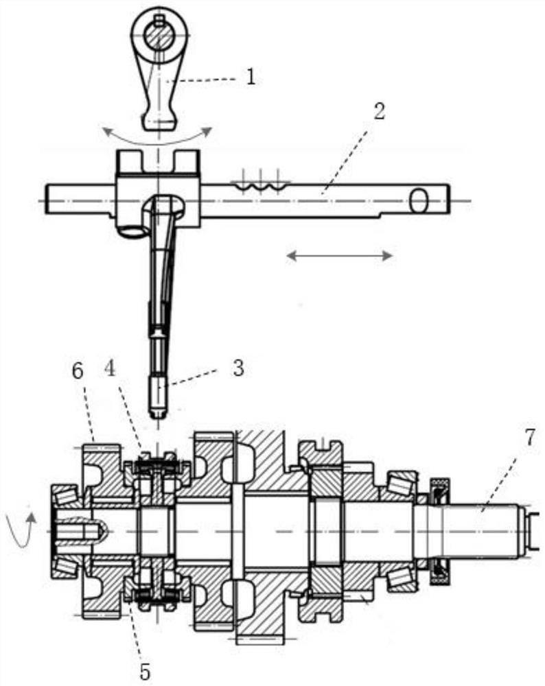
[0002] FIG. 1 is a typical transmission fork shifting structure. The shift paddle 1 is driven back by an external actuator Swing around the center. The shift fork shaft 2 and the shift fork 3 are assembled into a whole, and the swing of the shift head 1 will drive the shift fork 3 and the fork shaft 2 perform linear motion. The shift fork 3 also drives the meshing tooth sleeve 4 to perform linear motion. The left side of the meshing tooth sleeve in Figure 1 There is a meshing tooth on each of the right sides. Taking the meshing tooth 5 on the left side as an example, when the meshing tooth sleeve 4 moves to the left, it will interact with the meshing tooth 5...

Examples

Embodiment Construction

[0044] Step 3, calculate D (corresponding to S06 in Figure 3), D is the total stroke of the shifting system, D=|D_L0|+|D_R0|;

[0047] Specifically, the total wear setting value is set according to the size value of the shifting system, and the trend is: if shifting

[0048] In this embodiment, the calculation method of the total wear amount of the shifting system is clarified, when ΔD is greater than the total wear

[0050]ΔD_L0=|D_L0|‑|D_L*|, wherein, ΔD_L0 is the wear amount of the left side of the shifting system, D_L* is

[0052]△D_L0=|D_L0|‑|D_L*|=|‑8.5|‑|‑8|=0.5mm;

[0053]ΔD_R0=|D_R0|‑|D_R*|, wherein, ΔD_R0 is the wear amount of the right side of the shifting system, and D_R* is

[0055] Then △D_R0=|D_R0|‑|D_R*|=|8.5|‑|8|=0.5mm;

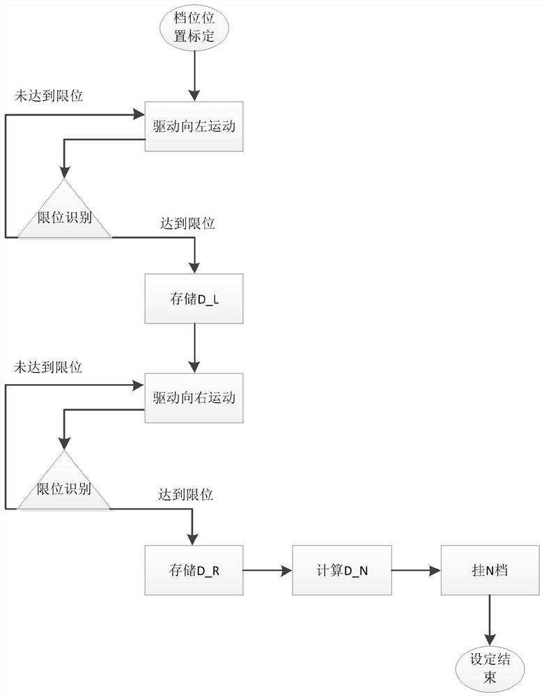
[0059] D_L is the gear setting position to the left,

[0060] D_N is a neutral setting position that does not consider wear compensation,

[0061] D_R is the gear setting position to the right,

[0071] A regular start-up program is set in the gea...