Multi-joint bionic mechanical chela with autonomously-distributed power

A bionic machine, multi-joint technology, applied in the field of bionic robots, can solve the problems of single movement mode, inconvenient installation and maintenance, less freedom, etc., and achieve the effects of convenient installation and disassembly, improved work reliability, and reduced wear and tear failures.

Pending Publication Date: 2018-10-12
长沙紫宸科技开发有限公司
View PDF13 Cites 0 Cited by
  • Summary
  • Abstract
  • Description
  • Claims
  • Application Information

AI Technical Summary

Problems solved by technology

[0005] For example, a paper titled "Design and Realization of Bionic Crab Robot" was published in the 12th issue of "Mechanics and Electronics" in 2009, which reported a kind of bionic crab robot, which has two claws , each pincer has 3 joints, which are respectively driven by 3 servo motors, which can realize functions such as picking up and carrying; but this type of bionic pincer has the following defects: one is that only the clamp of the pincer is imitated on this type of bionic pincer The function of picking and other functions has not realized the multiple bionic functions of the pincers and defense in the full sense; second, this type of bionic pincers has no power of its own, and the power is concentrated on the main frame of the robot, which needs to be transmitted to the bionic pincers through cables First, it is easy to be paralyzed due to the wear and tear of the connecting cable caused by frequent movements; third, the integral centralized power supply has the problems of long charging time and low charging efficiency; fourth, this type of bionic pliers is connected to the power on the main frame, and installation and maintenance are mostly inconvenient
[0006] CN201610277479.2 discloses a multipurpose bionic crab robot, which includes a right clamp module and a left clamp module; the right clamp module is driven by a right clamp drive motor, a right clamp drive pinion, a right clamp drive gear, Right tong swivel arm, right tong primary drive hydraulic lever, right pivot pin, right tong primary drive arm, right tong secondary drive hydraulic lever, right tong secondary drive arm, right Side clamp third-stage drive hydraulic rod, right clamp third-stage drive arm, rotary cutting blade, auxiliary camera, flat-blade automatic screwdriver, cross automatic screwdriver, rotary cutting blade driving eccentric disk, rotary cutting blade driving disc motor, rotary The cutting blade drives the first connecting rod, the rotary cutting blade drives the second connecting rod, and the rotary cutting knife teeth; the left clamp module adopts a similar structure to realize the function of stretching the saw blade; the patent uses mechanical and hydraulic methods to realize the sawing of the bionic pincers. It has the characteristics of large clamping force and strong sawing ability, but it has the following defects: First, the power source is concentrated on the main frame of the bionic machine, and the hydraulic power system on the main frame of the robot needs to provide the power of the claws. Joint hydraulic power is easily paralyzed due to the wear and tear of connecting cables or hydraulic pipes; second, its integrated centralized power supply is arranged on the main body of the bionic robot, which has the problems of long charging time and low charging efficiency; third, the use of linear cylinders The joint movement and the drive present a nonlinear relationship, which leads to a complex control system; fourth, the bionic pliers and the connecting cables or / and hydraulic pipes arranged in it must be directly connected to the main frame of the robot, which is extremely inconvenient for disassembly and maintenance
[0007] CN201410581468.4 discloses a bionic crab robot, wherein the claw system includes a rack, and a claw main body is respectively installed at the symmetrical positions on the left and right sides of the rack, and each claw main body is composed of a fixed frame, a motor frame, swing steering gear, two connecting cards, tray, grasping steering gear, two key-shaped gear rods, two claw rods and two connecting rods, and the mechanical method of the connecting rod mechanism is used to realize the clamping of the bionic pincers Function, there are the following problems: First, the power source is concentrated on the main frame of the bionic machine, and the mechanical structure of multiple parts is used to transmit power, which is complicated in structure and poor in reliability; Poor ability under complex working conditions; third, the integrated centralized power supply is arranged on the main body of the bionic robot, which has the problems of long charging time and low charging efficiency; fourth, it is inconvenient to install and maintain

Method used


Image

  • Multi-joint bionic mechanical chela with autonomously-distributed power
  • Multi-joint bionic mechanical chela with autonomously-distributed power
  • Multi-joint bionic mechanical chela with autonomously-distributed power

Examples


Embodiment 1

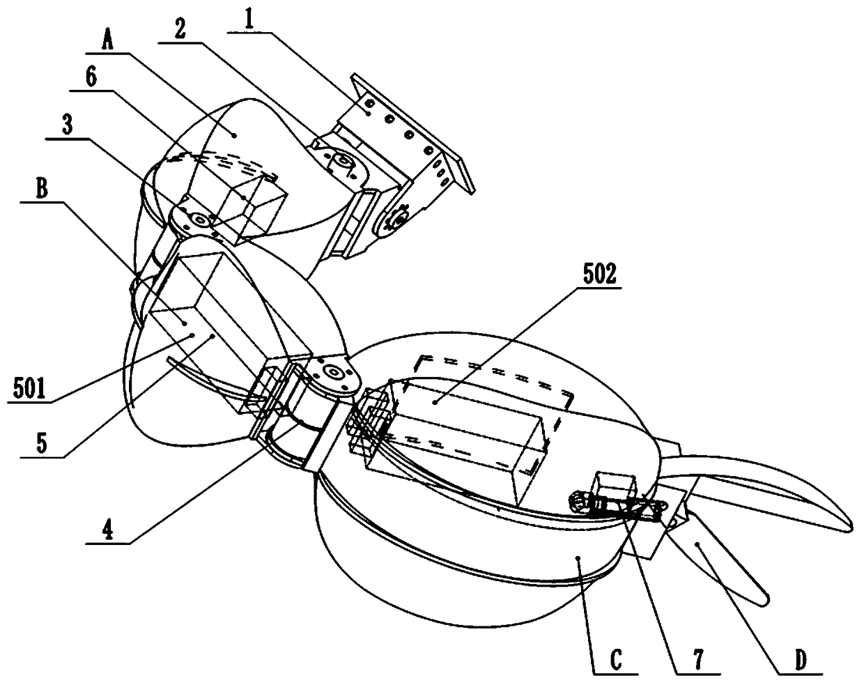
[0033] Reference figure 1 , figure 2 , This embodiment of the multi-joint bionic mechanical chelator with autonomously distributed power includes the connecting frame 1, the three-dimensional joint 2, the chelating section A, the two-dimensional joint I3, the chelating shield section C, the clamp section D, the power device 5, and the electric control device. 6; The three-dimensional joint 2 is fixed on the connecting frame 1 and connected to the chelating section A, the cheating section A is connected to the chelating shield section C through the two-dimensional joint Ⅰ3, and the clamp section D is fixed to the chelating shield section C. The power unit 5 includes a battery pack 501 and battery pack Ⅱ502 are respectively fixed in the cavity of chelating section A and chelating shield section C. The electric control device 6 is fixed in the cavity of chelating shield section C. The electric control device 6 is connected to the power device 5 and the three-dimensional joint 2 res...

Embodiment 2

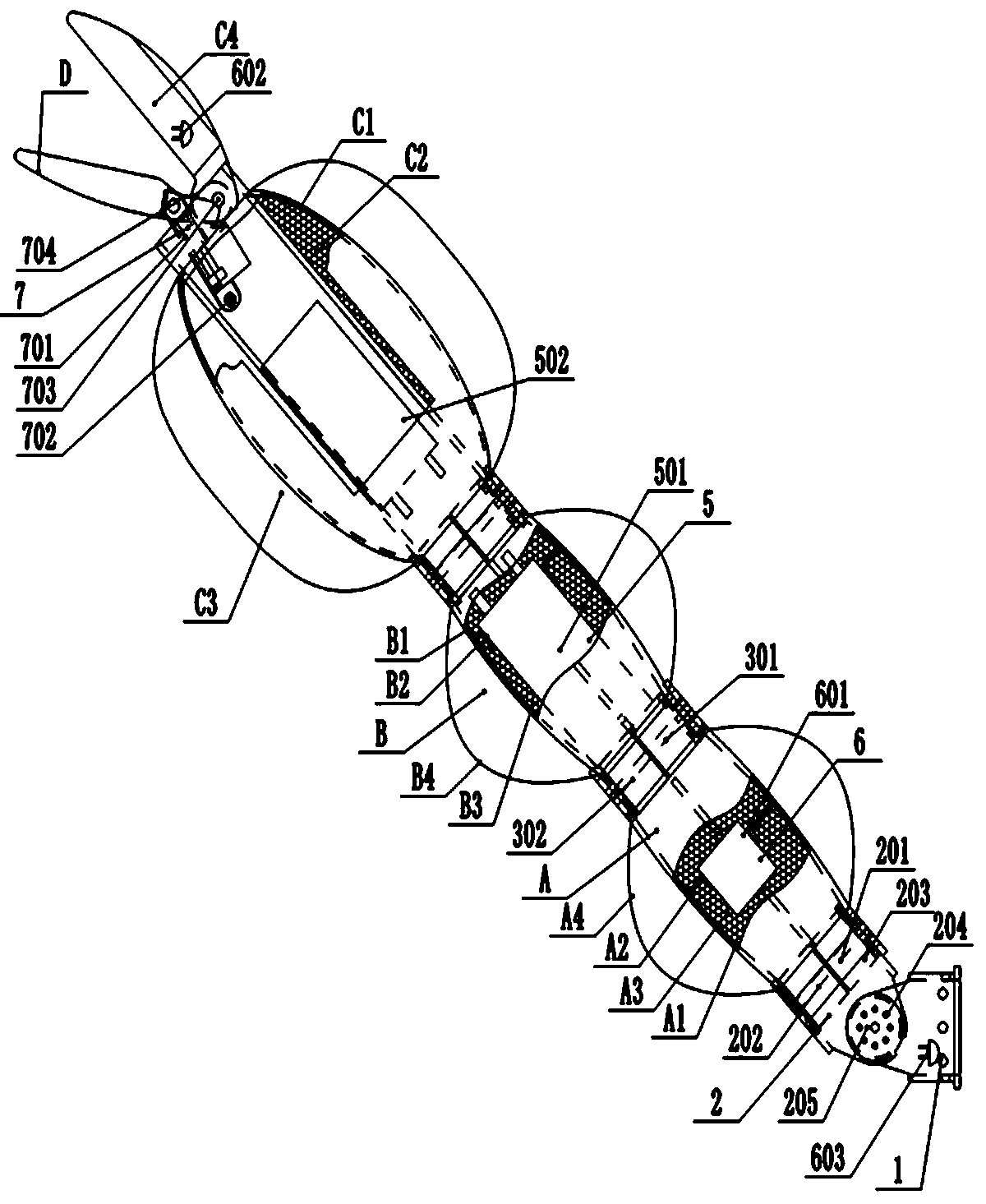
[0039] Reference image 3 , Figure 4 , This embodiment of the multi-joint bionic mechanical chelating forceps with autonomously distributed power includes the connecting frame 1, the three-dimensional joint 2, the chelating section A, the two-dimensional joint Ⅰ3, the chelating section B, the two-dimensional joint II4, the chelating shield section C, and the clamp movement. Mechanism 7, forceps section D, power device 5, electric control device 6; three-dimensional joint 2 is fixed on the connecting frame 1 and connected to the chelating section A, which is connected to the chelating section B through the two-dimensional joint I3, and the cheating section B passes through The two-dimensional joint Ⅱ 4 is connected to the chelating shield section C, and the chelating shield section C is connected to the clamp section D through the clamping mechanism 7. The power unit 5 mainly includes the battery pack I 501 and the battery pack Ⅱ 502, which are respectively fixed to the chelating...

Embodiment 3

[0046] Reference Figure 5 , Image 6 , Figure 7 The difference between the multi-joint bionic mechanical pliers with autonomously distributed power in this embodiment and the second embodiment is that: the mechanical pliers is additionally equipped with a swing saw 8, which is fixed on the upper middle of the chelating shield section C; the swing saw 8 includes a drive Motor 801, swing saw blade 802; the clamp section D adopts a sawtooth jaw; the charging port 602 adopts a wireless induction charging port, the electrical plug-in 603 adopts wireless Bluetooth for communication, and the reducer adopts a multi-stage In the planetary reducer, the driving motor adopts a stepping motor.


PUM


Abstract

The invention provides a multi-joint bionic mechanical chela with autonomously-distributed power. The multi-joint bionic mechanical chela comprises a chela section and a chela shield section. The multi-joint bionic mechanical chela is characterized in that the multi-joint bionic mechanical chela is further provided with a connecting frame, a power device, a pincer movement mechanism, a pincer section and an electric control device; the connecting frame, the chela section and the chela shield section are sequentially connected through joints; the power device is fixed to a cavity / cavities of the chela section or / and the chela shield section; the electric control device is fixed to a cavity / cavities of the quick-fitting connecting frame or / and the chela section or / and the chela shield section; the electric control device is correspondingly and electrically connected with the power device and the joints; and the pincer section is connected with the chela shield section through the pincermovement mechanism. The multi-joint bionic mechanical chela is simple in structure and convenient to mount and dismount; and the complete machine is high in working reliability.

Description

Technical field [0001] The invention relates to the technical field of bionic robots, in particular to a multi-joint bionic mechanical chelator with autonomously distributed power. Background technique [0002] Bionic intelligent machinery, as the name suggests, is an intelligent machinery or robot developed by scientific and technological workers imitating the structure or structure of natural organisms with unique characteristics. [0003] The scorpion's chelating forceps have multiple degrees of freedom, good flexibility, large clamping force, and shield-shaped defensive structure. It has obvious advantages in daily detection, feeding, attack, and defense; this kind of evolution has been developed for thousands of years Biological structure has a strong bionic significance for human activities, such as earthquake rescue, security protection, underwater construction, military investigation, and field exploration. [0004] At present, in the research and development of bionic machi...

Claims


Application Information

Patent Timeline
Patent Type & Authority Applications(China)
IPC IPC(8): B25J17/00B25J17/02B25J15/00B25J19/00B25J9/00B25J9/16
CPCB25J9/00B25J9/0009B25J9/16B25J15/00B25J17/00B25J17/02B25J19/00
Inventor 尹小林韩建英
Owner 长沙紫宸科技开发有限公司
Why Eureka
Try Eureka