
Rotatable lifting monitoring device convenient to maintain and install

A monitoring device, a technology of rotating and lifting, applied in the parts of color TVs, parts of TV systems, TVs, etc., can solve the problems of inconvenient maintenance, insufficient activity space, hidden dangers, etc., so as to facilitate maintenance work and solve hidden dangers. Effect

Inactive Publication Date: 2020-12-18
成都何星至享新能源科技有限公司
View PDF0 Cites 1 Cited by
  • Summary
  • Abstract
  • Description
  • Claims
  • Application Information

AI Technical Summary

Problems solved by technology

[0002] In order to achieve traffic control, the relevant departments will install monitoring equipment on the traffic road. During the installation process of the monitoring equipment at this stage, the staff need to climb above the lamp post for installation, which has certain potential safety hazards. Moreover, during the installation process, due to The staff is in a high-altitude position, the working space is limited, and the activity space is insufficient, which makes it very difficult to adjust the angle of the monitoring equipment, which brings great troubles to the installation work, and also brings great inconvenience to the subsequent maintenance.

Method used


Image

  • Rotatable lifting monitoring device convenient to maintain and install
  • Rotatable lifting monitoring device convenient to maintain and install
  • Rotatable lifting monitoring device convenient to maintain and install

Examples


Embodiment Construction

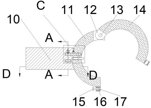
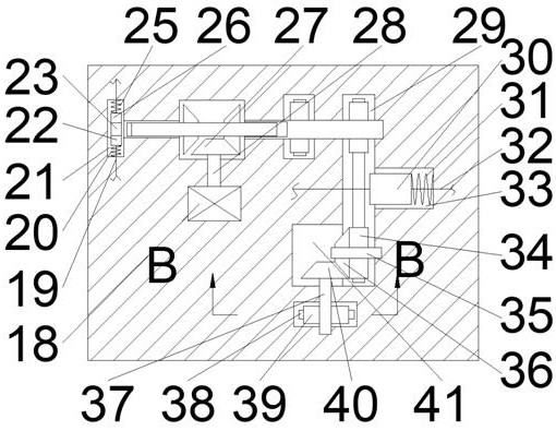
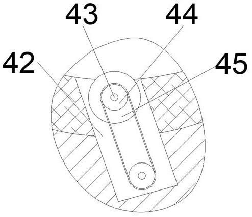
[0016] Combine below Figure 1-5 The present invention is described in detail, wherein, for the convenience of description, the orientations mentioned below are defined as follows: figure 1 The up, down, left, right, front and back directions of the projection relationship itself are the same.

[0017] A rotatable lifting monitoring device that is convenient for maintenance and installation described in conjunction with accompanying drawings 1-5 includes a carrier 10, the right end of the carrier 10 is fixedly connected with a fixed ring 11, and the fixed ring 11 is provided with an opening facing inward The lifting friction wheel cavity 65, the fixed ring 11 is provided with a lifting wheel cavity 59 located at the rear side of the lifting friction wheel cavity 65, and the rear end wall of the lifting wheel cavity 59 is connected with a lifting slider cavity 55, so The carrier 10 is provided with a forward and reverse chamber 52 located on the rear side of the lifting wheel ...


PUM


Abstract

The invention relates to the related field of monitoring equipment, and discloses a rotatable lifting monitoring device convenient to maintain and install. The device comprises a carrier. A fixed ringis fixedly connected to the right end surface of the carrier. A lifting friction wheel chamber with an inward opening is arranged in the fixed ring, and a lifting wheel chamber located on the rear side of the lifting friction wheel chamber is arranged in the fixed ring. A lifting sliding block chamber is formed in the rear end wall of the lifting wheel chamber in a communication manner, a forwardand reverse rotation chamber located on the rear side of the lifting wheel chamber is formed in the carrier, the monitoring equipment is fixed through an annular fixing device fixed to the side end of the monitoring equipment, then all gears inside the monitoring equipment are controlled to carry out engaged transmission by pulling corresponding pull ropes, a friction wheel can rotate through theinteraction force between magnets, so that the monitoring equipment is driven to freely slide upwards and downwards and circumferentially rotate on a lamp post, the installation and debugging of themonitoring equipment are implemented, the subsequent maintenance work is facilitated, the potential safety hazard of high-altitude operation is solved, and great convenience is brought to workers in work.

Description

technical field [0001] The invention relates to the related field of monitoring equipment, in particular to a rotatable lifting monitoring device which is convenient for maintenance and installation. Background technique [0002] In order to achieve traffic control, the relevant departments will install monitoring equipment on the traffic road. During the installation process of the monitoring equipment at this stage, the staff need to climb above the lamp post for installation, which has certain potential safety hazards. Moreover, during the installation process, due to The staff is in a high-altitude position, the working space is limited, and the activity space is insufficient, which makes it very difficult to adjust the angle of the monitoring equipment, which brings great troubles to the installation work, and also brings great inconvenience to the subsequent maintenance. . Contents of the invention [0003] The object of the present invention is to provide a rotatab...

Claims


Application Information

Patent Timeline
IPC IPC(8): F16M11/04F16M11/42H04N5/225
CPCF16M11/04F16M11/425H04N23/50
Inventor 李佳赫
Owner 成都何星至享新能源科技有限公司
Learn More