
Heat exchange core plate, total heat exchange module, air interchanger and air conditioner

A technology of full heat exchange and ventilation device, which is applied in the field of heat exchange core board, ventilation device, air conditioner, and full heat exchange module, and can solve the problems of short heat exchange time and low heat exchange efficiency

Pending Publication Date: 2020-12-18
GREE ELECTRIC APPLIANCES INC
View PDF0 Cites 1 Cited by
  • Summary
  • Abstract
  • Description
  • Claims
  • Application Information

AI Technical Summary

Problems solved by technology

[0004] It can be seen that the working efficiency of the total heat exchange core determines the working efficiency of the total heat exchanger product. In the prior art, the vertical cross flow of air between the layers is mostly used for heat exchange, and the heat exchange time is shorter than the heat exchange efficiency. Low; in order to improve the working efficiency of total heat exchanger products and reduce operating costs, a total heat exchange core with a higher heat exchange rate is urgently needed

Method used


Image

  • Heat exchange core plate, total heat exchange module, air interchanger and air conditioner
  • Heat exchange core plate, total heat exchange module, air interchanger and air conditioner
  • Heat exchange core plate, total heat exchange module, air interchanger and air conditioner

Examples


Embodiment 1

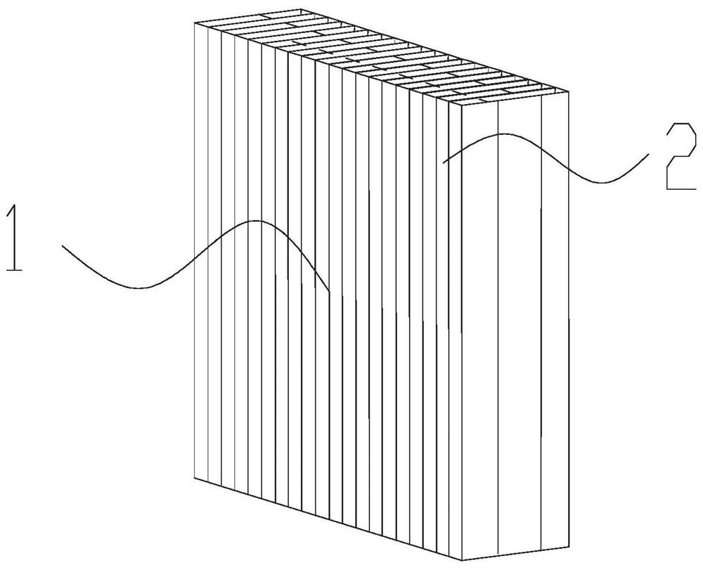
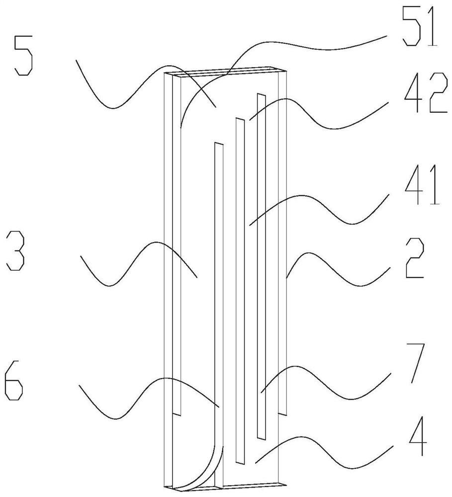
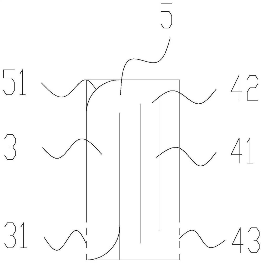
[0037] This embodiment provides a heat exchange core plate. Flow channels are formed on one side of the heat exchange core plate. The flow channels include a first flow channel in the first flow direction, a second flow channel in the second flow direction, and a flow channel connected to the first flow channel and the turning channel between the second flow channel; the outer guide edge of the turning channel is formed with an inclined guide surface, and the inclined guide surface extends from the first flow channel side to the second flow channel side; and in the second flow channel A plurality of parallel sub-channels are formed, and each sub-channel is formed at the end close to / connected with the diversion channel to communicate with the diversion channel, and the flow channel communication port is for the fluid flowing through the heat exchange core plate to flow in or out The connection structure; specifically, the flow channel communication openings of the multiple para...

Embodiment 2

[0045] This embodiment provides a heat exchange core plate. Specifically, the heat exchange core plate has a mirror-symmetrical structure with the heat exchange core plate described in Embodiment 1, and further has a mirror-image symmetrical flow structure with the heat exchange core plate in the embodiment. road structure. By forming a mirror-image symmetrical arrangement with the heat exchange core plate of Example 1, a heat exchange core plate structure similar to but not identical to that of Example 1 is formed; further, the heat exchange core plate in the embodiment The plates are alternately stacked with the heat exchange core plates in this embodiment to form a total heat exchange module. Specifically, the first flow passages of the multiple heat exchange core plates are arranged on the same side of the total heat exchange module; the second flow passages of the multiple heat exchange core plates are arranged on the same side of the total heat exchange module.

[0046]...

Embodiment 3

[0053] This embodiment provides a total heat exchange and ventilation device, the total heat exchange and ventilation device is equipped with the heat exchange core plate described in embodiment 1 or the total heat exchange module described in embodiment 2; further optimized, when the total heat exchange When the heat exchange and ventilation device is equipped with a total heat exchange module in which the heat exchange core plates alternately form the flow layer of the turbid air and the flow layer of the fresh air, the total heat exchange and ventilation device is also equipped with an indoor turbid air inlet duct, an indoor turbid air The wind outlet wind channel, the outdoor fresh air inlet air channel and the outdoor fresh air outlet air channel; the indoor turbid air flow inlet of the turbid wind flow layer is connected to the indoor turbid wind inlet air channel; the indoor turbid air flow outlet of the turbid wind flow layer is connected to the The indoor dirty air out...


PUM


Abstract

The invention provides a heat exchange core plate, a total heat exchange module, an air interchanger and an air conditioner. A first flow channel, a second flow channel and a steering flow channel connected between the first flow channel and the second flow channel are formed in one side face of the heat exchange core plate; an inclined flow guide surface is formed on the outer flow guide edge ofthe steering flow channel, and extends from a first flow channel side to a second flow channel side; the second flow channel comprises a plurality of parallel sub-flow channels; a flow channel communicating opening communicated with the steering flow channel is formed in the end, close to / connected with the steering flow channel, of each sub-flow channel; and the flow channel communicating openings of the plurality of parallel sub-flow channels are formed in the mode that the opening direction corresponds to the inclination direction of the inclined flow guide surface in a staggered way. By means of the technical scheme, under the cooperation of the inclined flow guide surface and the flow channel communicating openings formed in a staggered mode, fluid flowing out of the steering flow channel is evenly distributed into the plurality of sub-flow channels, so that even distribution of the fluid is achieved; and uniform heat exchange in the heat exchange process is further ensured.

Description

technical field [0001] The invention relates to a total heat exchanger for an air conditioner, in particular to a heat exchange core plate, a total heat exchange module, a ventilation device and an air conditioner. Background technique [0002] With the development of society, people's living standards have been greatly improved, and air conditioners have become one of the requisite household appliances in people's lives. However, the traditional air conditioner has a single function and cannot meet people's pursuit of high-quality healthy life. The outbreak of the new crown virus has aroused people's attention to healthy life. Therefore, the development of healthy and energy-saving air conditioners has become one of the future development trends. [0003] The existing total heat exchange core is used as air-conditioning exhaust ventilation equipment. Its working principle is: when the product is working, when the indoor exhaust air and the fresh air flow through the core ...

Claims


Application Information

Patent Timeline
Patent Type & Authority Applications(China)
IPC IPC(8): F24F1/0007F24F1/0035F24F1/0067F24F12/00F28D9/04
CPCF24F1/0007F24F12/001F28D9/04F24F1/0035F24F1/0067
Inventor 王于曹汪展展高玉平孙子超陈立伟王宪吉
Owner GREE ELECTRIC APPLIANCES INC
Learn More