A cable laying device for cable trench

A cable laying and cable trenching technology, applied in cable laying equipment, transportation and packaging, thin material handling, etc., can solve the problems of low laying efficiency, consuming a lot of manpower and material resources, etc. Effect

Active Publication Date: 2021-10-15
SHANGHE COUNTY POWER SUPPLY CO STATE GRID SHANDONG ELECTRIC POWER CO +1
View PDF11 Cites 0 Cited by
  • Summary
  • Abstract
  • Description
  • Claims
  • Application Information

AI Technical Summary

Problems solved by technology

[0002] Cables are important power transmission equipment. In the process of power transmission, cables often need to be routed underground, so it is necessary to dig underground to construct cable trenches; cable trenches are underground pipelines for laying and replacing power or telecommunication cable facilities. The enclosure structure of the cable facilities has rectangular, circular, arched and other pipe structures. The cable trench structure in the prior art is generally a trench with a cover plate, and a cable support for laying cables is arranged in the trench. Then manually lay the cable. When laying the cable in the cable trench, many people are required to pass the cable, that is, from one end to the other. For the cable laying work with a shorter distance, fewer people are needed; For large-area cable laying work, especially in cable trenches with narrow spaces and complicated wiring, it often takes a lot of manpower and material resources, and the laying efficiency is low

Method used


Image

  • A cable laying device for cable trench
  • A cable laying device for cable trench
  • A cable laying device for cable trench

Examples


Embodiment Construction

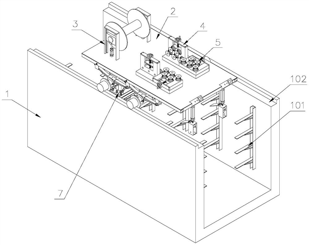
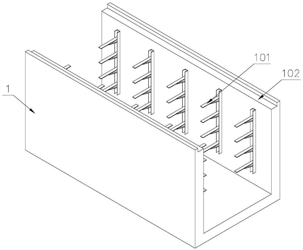
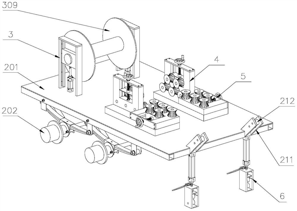
[0047] Attached below Figure 1-13 , clearly and completely describe the technical solutions in the embodiments of the present invention, obviously, the described embodiments are only some of the embodiments of the present invention, not all of them. Based on the embodiments of the present invention, all other embodiments obtained by persons of ordinary skill in the art without making creative efforts belong to the protection scope of the present invention.

[0048] In describing the present invention, it should be understood that the terms "longitudinal", "transverse", "upper", "lower", "front", "rear", "left", "right", "vertical", The orientations or positional relationships indicated by "horizontal", "top", "bottom", "inner", "outer", etc. are based on the orientations or positional relationships shown in the drawings, and are only for the convenience of describing the present invention, rather than indicating or It should not be construed as limiting the invention by impl...


PUM


Abstract

The invention discloses a cable laying device for a cable trench, which comprises a cable trench, a mobile vehicle arranged on the cable trench, a wire-laying device arranged on the upper side of the rear part of the mobile vehicle, and a laying device arranged on the lower side of the front part of the mobile vehicle. Wire device, the mobile car includes a car body, a wheel shaft arranged at the lower part of the car body, moving wheels arranged at both ends of the wheel shaft, and a motor arranged at the lower part of the car body; The support plate on the frame; the wire laying device includes a threading frame arranged on the upper part of the cable, a supporting wheel arranged inside the threading frame, and a crimping wheel arranged on the upper part of the supporting wheel. In the present invention, a wire-laying device is provided on the upper side of the mobile vehicle, and a wire-laying device is provided on the lower side of the mobile vehicle. When the mobile vehicle moves on the cable trench, the wire-laying device releases the cables. Laying on the cable rack improves the efficiency of cable laying and reduces the labor intensity of workers.

Description

technical field [0001] The invention belongs to the technical field of cable laying construction, in particular to a cable laying device for cable trenches. Background technique [0002] Cables are important power transmission equipment. In the process of power transmission, cables often need to be routed underground, so it is necessary to dig underground to construct cable trenches; cable trenches are underground pipelines for laying and replacing power or telecommunication cable facilities. The enclosure structure of the cable facilities has rectangular, circular, arched and other pipe structures. The cable trench structure in the prior art is generally a trench with a cover plate, and a cable support for laying cables is arranged in the trench. Then manually lay the cable. When laying the cable in the cable trench, many people are required to pass the cable, that is, from one end to the other. For the cable laying work with a shorter distance, fewer people are needed; Fo...

Claims


Application Information

Patent Timeline
Patent Type & Authority Patents(China)
IPC IPC(8): H02G1/06B65H49/32B65H49/30B65H59/20B65H59/22B65H57/14B65H57/00
CPCB65H49/30B65H49/325B65H57/00B65H57/14B65H59/20B65H59/22H02G1/06
Inventor 宋茂光翟伟李辛鹏刁守斌赵涛韩圣
Owner SHANGHE COUNTY POWER SUPPLY CO STATE GRID SHANDONG ELECTRIC POWER CO
Why Eureka
Try Eureka