Auxiliary pressure-dividing cable trench

A cable trench and voltage dividing technology, which is applied in the installation of cables, ground cables, electrical components, etc., can solve the problems of structural deformation of the cover plate and reduction of the strength of the cover plate, so as to prolong the service life, protect from damage, Good cooling effect

Active Publication Date: 2021-12-07
TECH INFORMATION CENT SPIC HENAN ELECTRIC POWER CO LTD +1
View PDF0 Cites 0 Cited by
  • Summary
  • Abstract
  • Description
  • Claims
  • Application Information

AI Technical Summary

Problems solved by technology

[0004] The purpose of the present invention is to solve the disadvantages in the prior art that the grid structure will cause the strength of the cover plate to decrease. When the cover plate bears the pressure of the vehicle for a long time, the structure of the cover plate will be obviously deformed. Voltage divider cable trench

Method used


Image

  • Auxiliary pressure-dividing cable trench
  • Auxiliary pressure-dividing cable trench
  • Auxiliary pressure-dividing cable trench

Examples


Embodiment 1

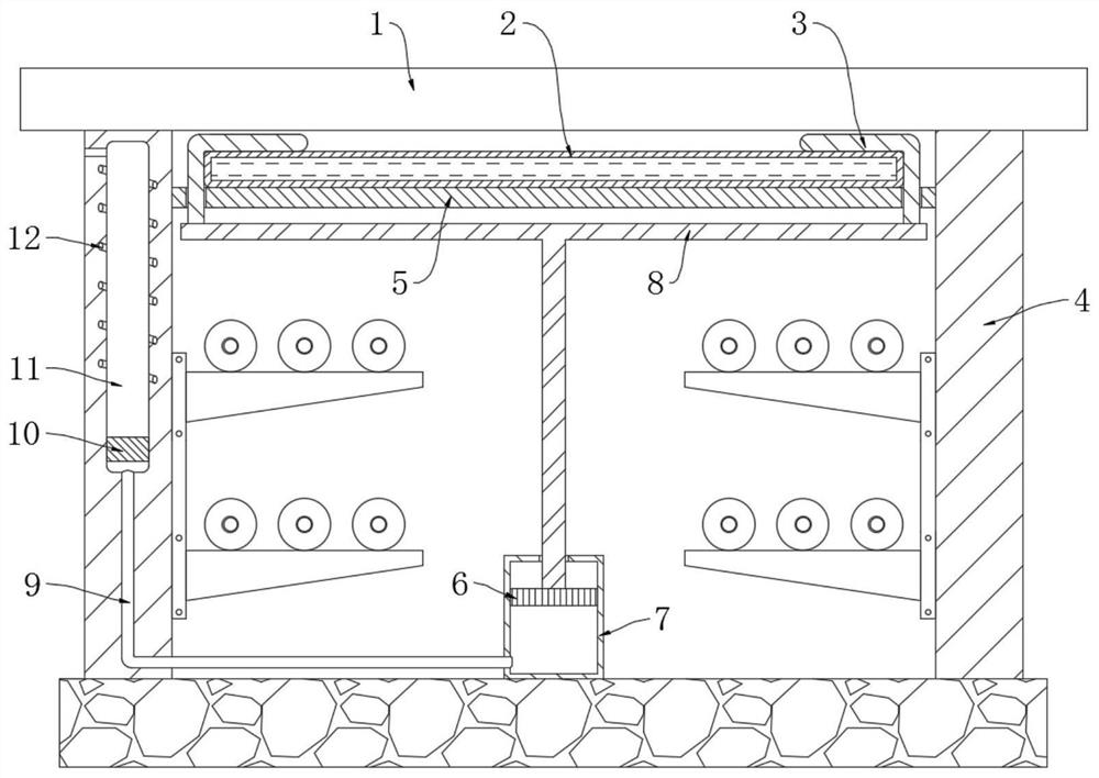
[0024] refer to figure 1 , an auxiliary pressure-dividing cable trench, including a trench body, a cover plate 1 and two side plates 4, a limit cylinder 7 is fixedly arranged in the trench body, and a sliding plate 6 is arranged for sealing and sliding in the limit cylinder 7, and on the slide plate 6 A T-shaped plate 8 is fixedly connected, and two L-shaped pressure plates 3 are symmetrically installed on the upper surface of the T-shaped plate 8, and a pressure dividing plate 5 is fixedly supported between the two side plates 4, and a capsule body 2 is placed on the pressure dividing plate 5. Both L-shaped pressing plates 3 include a horizontal section and a vertical section, the horizontal sections of the two L-shaped pressing plates 3 are located above the capsule body 2, and the vertical sections of each L-shaped pressing plate 3 slide through the dividing plate 5, wherein A trigger mechanism is also arranged in a side plate 4 .

[0025] In this embodiment, the trigger m...

Embodiment 2

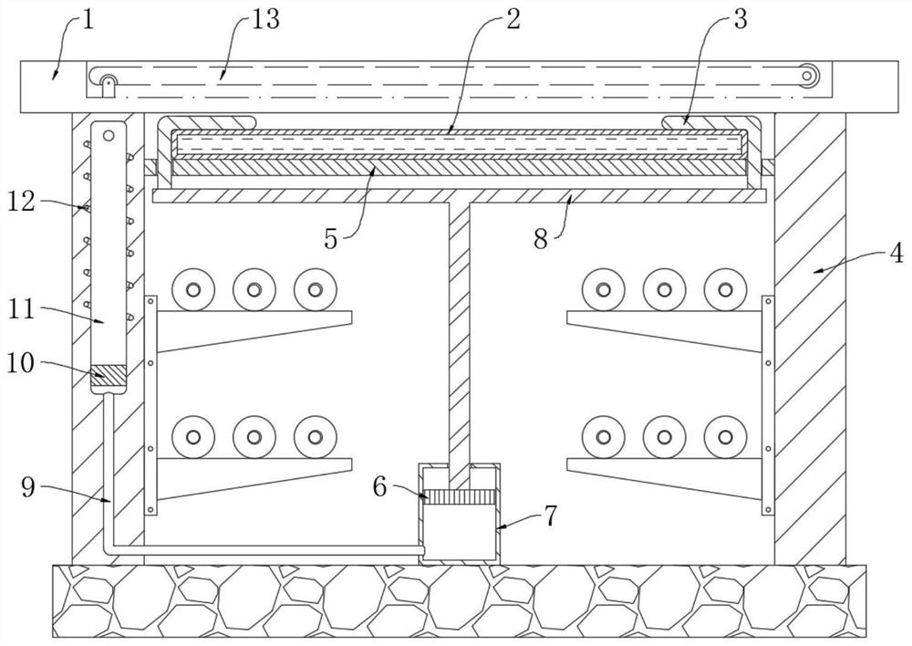
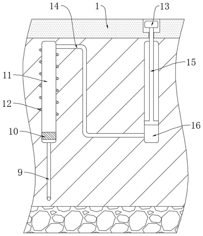
[0032] refer to Figure 2-5 The difference between this embodiment and Embodiment 1 is that a waterproof groove 16 is provided in the side plate 4, and a strut 15 is sealed and slidably installed in the waterproof groove 16, and the upper end of the strut 15 penetrates the corresponding side plate 4 and extends to On the top of the ditch body, the side wall of the cover plate 1 is connected with a gear rod 13 through the rotating shaft, and the end of the gear rod 13 away from the rotating shaft is slidably connected with the top of the pole 15, and the gear rod 13 is located on two adjacent cover plates 1 between, and the gear rod 13 is flush with the cover plate 1.

[0033] In this embodiment, a pressure-resistant pipe 14 communicates between the lower end of the waterproof groove 16 and the upper end of the vertical groove 11, and the pressure-resistant pipe 14 is a hard PVC pipe.

[0034] This embodiment can illustrate its functional principle through the following operat...


PUM


Abstract

The invention discloses an auxiliary pressure-dividing cable trench, which includes a trench body, a cover plate and two side plates, a limit cylinder is fixedly arranged in the trench body, a sliding plate is sealed and slid inside the limit cylinder, and the A T-shaped plate is fixedly connected to the sliding plate, and two L-shaped pressure plates are symmetrically installed on the upper surface of the T-shaped plate, and a pressure dividing plate is fixedly supported between the two side plates, and a capsule is placed on the pressure dividing plate. Both of the two L-shaped pressing plates include a horizontal section and a vertical section, the horizontal sections of the two L-shaped pressing plates are located above the capsule, and the vertical sections of each of the L-shaped pressing plates slide through the dividing plate, One of the side panels is also provided with a trigger mechanism. The invention does not affect the ventilation of the cable trench under the condition of no vehicle passing, and when a vehicle passes through the cover plate, the device will automatically rigidly support the middle part of the cover plate to avoid damage to the structure of the cover plate.

Description

technical field [0001] The invention relates to the technical field of electric power protection equipment, in particular to an auxiliary voltage dividing type cable trench. Background technique [0002] With the improvement of urban planning, when laying power cables at long distances, the power cables are usually laid in the form of cable trenches. After the power cables are laid, the construction personnel will use thick steel plates, concrete pouring plates, composite plates and other materials The board seals the cable trench. This sealing method can achieve a good waterproof effect, but reduces the ventilation of the cable trench. In high temperature weather, especially in summer when the power load is large, the heat of the power cable is serious, and the conductor An increase in temperature will lead to an increase in its resistance, which further aggravates the heating of the power cable, forming a vicious circle, which not only increases the aging speed of the powe...

Claims


Application Information

Patent Timeline
Patent Type & Authority Patents(China)
IPC IPC(8): H02G9/02
CPCH02G9/02H02G9/025
Inventor 肖洪辉余磊
Owner TECH INFORMATION CENT SPIC HENAN ELECTRIC POWER CO LTD
Why Eureka
Try Eureka