
Asynchronous starting permanent magnet auxiliary type synchronous reluctance motor

A synchronous reluctance motor and permanent magnet technology, applied in synchronous machines, synchronous motors with stationary armatures and rotating magnets, magnetic circuit shape/style/structure, etc., can solve high manufacturing costs, magnetic circuit design permanent magnets Problems such as installation obstruction and low saliency rate

Active Publication Date: 2020-12-18
石镇德
View PDF23 Cites 11 Cited by
  • Summary
  • Abstract
  • Description
  • Claims
  • Application Information

AI Technical Summary

Problems solved by technology

[0003] However, the existing permanent magnet synchronous reluctance motors usually use NdFeB magnets, which have disadvantages such as high manufacturing costs and high temperature demagnetization.
In addition, the existing permanent magnet synchronous reluctance motor has a low salient pole ratio
In addition, in existing permanent magnet synchronous reluctance motors, the motor shaft is usually installed directly on the rotor (the motor shaft is installed through the rotor). This installation method hinders the magnetic circuit design of the rotor and the installation of permanent magnets.

Method used


Image

  • Asynchronous starting permanent magnet auxiliary type synchronous reluctance motor
  • Asynchronous starting permanent magnet auxiliary type synchronous reluctance motor
  • Asynchronous starting permanent magnet auxiliary type synchronous reluctance motor

Examples


Embodiment Construction

[0024] In order to solve the above-mentioned problems in the prior art, the present invention adopts a new motor rotor structure. In the new rotor structure, the through hole for installing the motor shaft on the rotor is removed, end covers are arranged at both ends of the rotor, the motor shaft is arranged on the end covers, and the motor shaft does not penetrate the rotor. This fundamentally solves the design difficulty of the permanent magnet synchronous reluctance motor, and can greatly increase the setting capacity of the permanent magnet.

[0025] In order to enable those skilled in the art to better understand the present invention, specific embodiments of the present invention will be described in detail below in conjunction with the accompanying drawings.

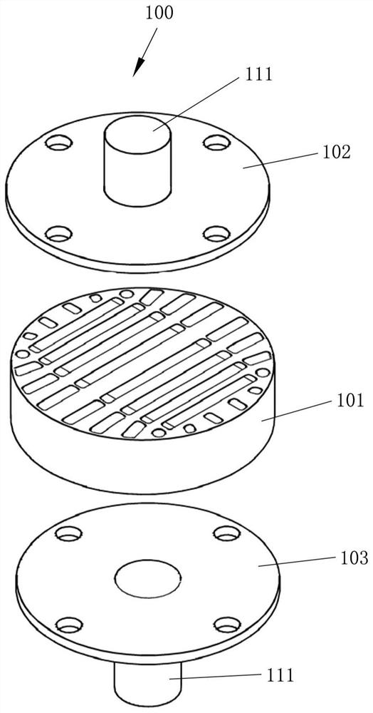
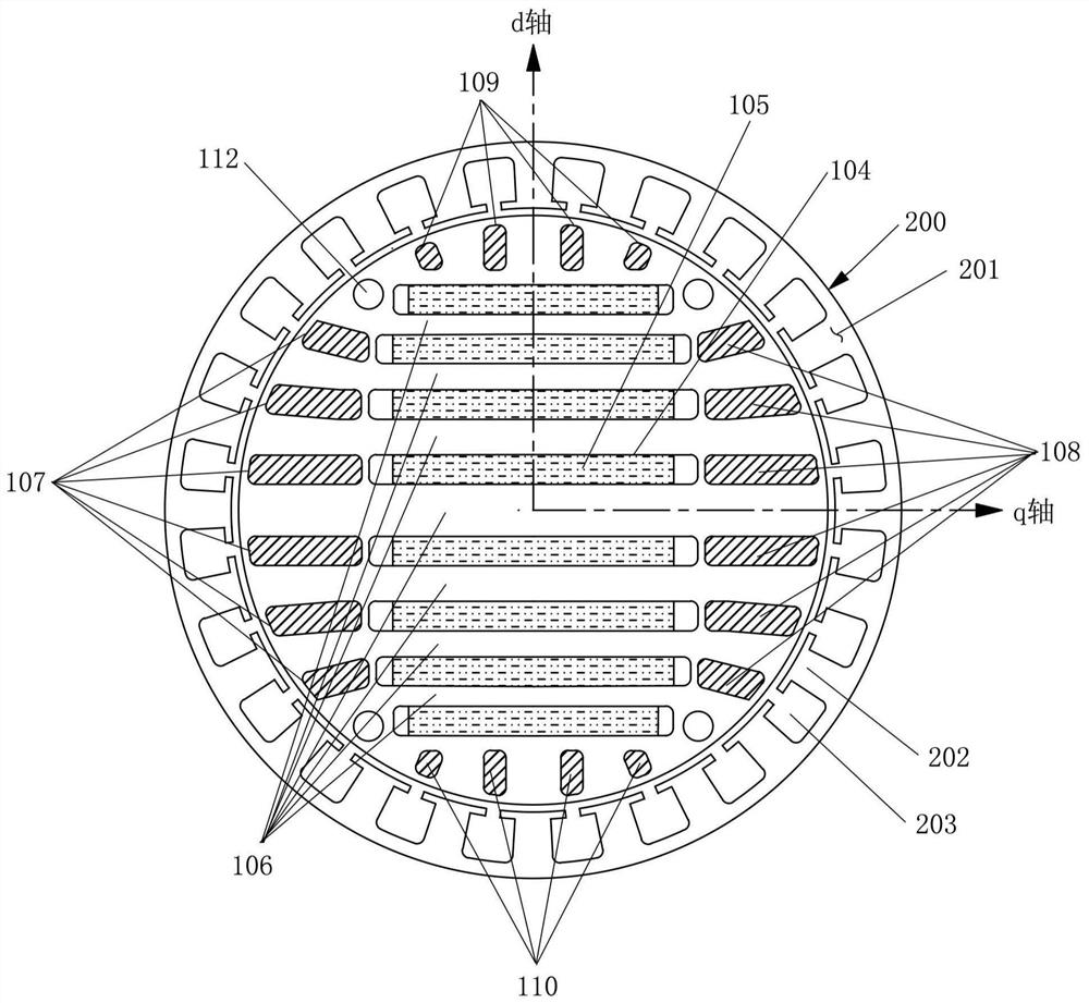
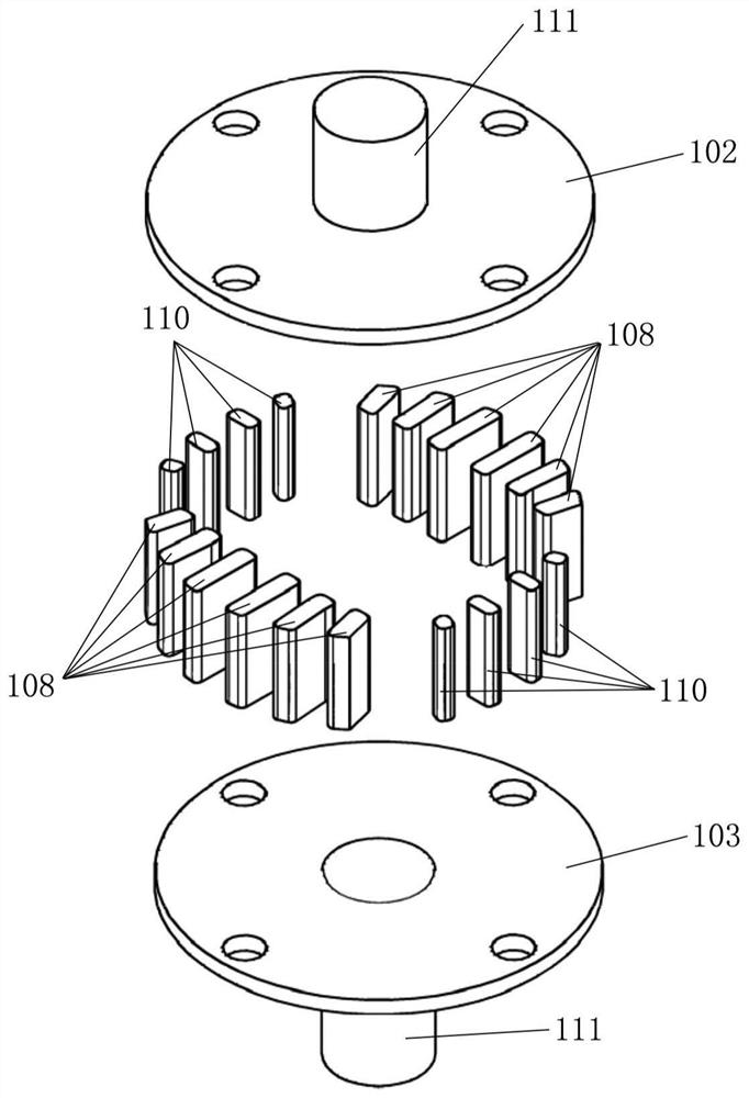
[0026] figure 1 It is an exploded schematic view of the rotor assembly of the asynchronous start permanent magnet assisted synchronous reluctance motor according to the present invention, figure 2 is a radial c...


PUM


Abstract

The invention provides an asynchronous starting permanent magnet auxiliary synchronous reluctance motor. The permanent magnet auxiliary synchronous reluctance motor comprises a stator assembly and a rotor assembly which are coaxially arranged, the rotor assembly comprises a cylindrical rotor core, a first end cover and a second end cover, a plurality of first magnetic isolation grooves which are parallel to one another and penetrate through the rotor core in the axial direction are formed in the rotor core, magnetic steel serving as a permanent magnet is installed in each first magnetic isolation groove, and a plurality of second magnetic isolation grooves which penetrate through the rotor core in the axial direction are formed in the area close to the outer edge of the rotor core, a second magnetic isolation groove is arranged between two ends of each first magnetic isolation groove and the outer edge of the rotor core, a first non-magnetic conductive strip is arranged in each secondmagnetic isolation groove, the first end cover and the second end cover are respectively fixed at two ends of the rotor core along the axial direction, and the motor shaft is arranged on the first endcover and the second end cover.

Description

technical field [0001] The invention belongs to the field of permanent magnet synchronous reluctance motors. Specifically, the invention relates to an asynchronous start permanent magnet assisted synchronous reluctance motor with low cost, safe and reliable structure, good starting performance and excellent speed stability. Background technique [0002] Permanent magnet synchronous reluctance motor is a combination of permanent magnet motor and synchronous reluctance motor. It has remarkable energy-saving effect, good magnetic field weakening effect, and is suitable for high, medium, low speed and full speed range. [0003] However, the existing permanent magnet synchronous reluctance motors usually use NdFeB magnets, which have disadvantages such as high manufacturing costs and high temperature demagnetization. In addition, the existing permanent magnet synchronous reluctance motor has a low saliency ratio. In addition, in existing permanent magnet synchronous reluctance m...

Claims


Application Information

Patent Timeline
IPC IPC(8): H02K21/46H02K21/14H02K1/28H02K1/27
CPCH02K21/46H02K21/14H02K1/28H02K1/2706Y02T10/64
Inventor 石镇德
Owner 石镇德
Learn More